
 |
How to make a Balanced Mono Sum cable |
Post Reply 
|
Page 123 4> |
| Author | |
opus jody 
Young Croc 
Joined: 06 June 2006 Location: United Kingdom Status: Offline Points: 1246 |
 Post Options Post Options
 Thanks(0) Thanks(0)
 Quote Quote  Reply Reply
 Topic: How to make a Balanced Mono Sum cable Topic: How to make a Balanced Mono Sum cablePosted: 29 March 2011 at 1:15pm |
|
Rrrright, time to make this into a thread, cos it's so useful.
yes, you can make a mono sum cable with resistors, but it's fiddly, and it muddies the sound up. I've tested it, and 'left only' sounds better than a resistored mono sum. anyone can test this. a better solution is this balanced mono sum. However, it only works between 2 balanced outputs and a single mono balanced input, and it needs to be labled up, as it's a mutant, single purpose cable. it works equally well mono summing bass, from crossover outputs to amp, and as a full range mono sum between balanced outputs of a mixer, and an amp channel, for example, for mono summing one DJ monitor, or for a mono speaker stack. to understand how it works, you need to understand how your balanced input works. It takes one 'in phase' signal (normally from pin 2 of your XLR) and it takes one anti phase (inverted) signal (normally from pin 3 of your XLR) . it then inverts the anti-phase signal, and sums it with the in-phase signal, boosting the signal by 6dB or something, and also, as both signals have picked up 'noise' on the way to it's destination, but as one of the cores is inverted, the 'noise gets inverted too, and if you add '+noise' to '-noise' then the 'noise' cancels itself out, giving you more music, and no 'noise'. got it? right, so if you were to feed '+left signal' into pin 2, and '-right' signal into pin 3, then the unbalancing circuitry would invert the '-right' signal, resulting in '+right', and then sum it with the '+left' signal, resulting in mono signal going into your device. That's the complicated bit, the actual cable is easy to make. what you'll need is: amp/crossover with a balanced input mixer/crossover with 2 balanced outputs 2 female XLR's 1 male XLR 2 shortish lengths of fairly thin un-balanced patch cable and a normal balanced mic lead to take your signal to where it's got to go to. Start with the male XLR end, cos it's the most difficult. twist the 2 grounds together tight, and tin them together. (i find it helps to do this too long, then cut it to length afterwards) strip & tin the 2 positive cores of the unbalanced patch cable, to the same length as the twisted grounds. in order to get the 2 cables into one (M) XLR, you might have to remove the plasic donut inside the black arse end of your (Neutric) connector. you can push it out with a screwdriver. Click the pics to make them bigger: 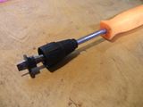 you may also have to trim off some of the rubbery bit too, to get your 2 wires in: 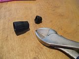 slide this bit over your cable assembly: 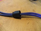 then solder the twisted grounds to pin 1 of your XLR. if you don't have a clamp of some sort, you can use any old bit of kit with an XLR input to hold your XLR steady. then solder the 2 positive cores to pin 2 and pin 3 of the XLR: 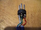 leave the XLR undone for the moment, it helps to see that you've got the cores the right way round. then the easy bit, solder 2 female XLR's onto the other ends of your 2 cables, making sure that the wire that is connected to pin 2 of the male XLR is connected to pin 2 of one of your female XLRs, and the wire that is connected to pin 3 of the male, is connected to pin 3 of the other female XLR. DON'T FORGET TO PUT THE XLR RUBBERY BIT ON 1ST!!!  both grounds go to pin 1 as usual. 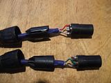 it's debatable whether the empty pin in each female XLR needs to be connected to gnd (pin 1). I never do, on outputs, and I've never had a problem. an empty pin on a balanced input should always be connected to gnd, but that's a different thing. double check that pin 2 goes to pin 2, pin 3 goes to pin 3, the pin 1's are all connected, and there's no stray 'hairs' anywhere, then put all your XLR casings together. If you removed the rubber donut from your male XLR, then the cable clamp bit won't work properly, so tape it up solid. do this with light coloured tape, and you can label it up too.  Aaand the finished cable: 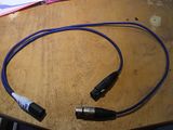 You can test it by panning your signal left & right on the mixer/crossover. as you'd expect, when panned, it gets a few dB's quieter. this bit of the cable is un-balanced, having only 2 cores in each bit, so keep it short. if you attach a mic cable to it though, the main bulk of the cable run will be balanced, as in there's 2 lots of audio that get summed, and any noise picked up will get cancelled, as per usual. As the mono sum in most mixers is probably the same, or similar, as the mono sum cable built with resistors, then this cable will probably sound clearer than a mono sum output on your mixer. see ya. Edited by opus jody - 12 February 2014 at 8:46am |
|
|
Improvised Hardware Music http://vimeo.com/user9389813/videos
|
|
 |
|
n8 
Registered User 
Joined: 09 October 2009 Status: Offline Points: 16 |
 Post Options Post Options
 Thanks(0) Thanks(0)
 Quote Quote  Reply Reply
 Posted: 29 March 2011 at 1:31pm Posted: 29 March 2011 at 1:31pm |
|
Cheers, thats really helpful

|
|
 |
|
SBC 
Registered User 
Joined: 25 November 2010 Status: Offline Points: 1266 |
 Post Options Post Options
 Thanks(0) Thanks(0)
 Quote Quote  Reply Reply
 Posted: 29 March 2011 at 1:38pm Posted: 29 March 2011 at 1:38pm |
|
what if you just sum the signal at an LMS?
|
|
|
F.T.S.S.
|
|
 |
|
opus jody 
Young Croc 
Joined: 06 June 2006 Location: United Kingdom Status: Offline Points: 1246 |
 Post Options Post Options
 Thanks(0) Thanks(0)
 Quote Quote  Reply Reply
 Posted: 29 March 2011 at 1:49pm Posted: 29 March 2011 at 1:49pm |
dunno mate. i'm an analog junky  no doubt that's fine, being in digital land. just loads more A/D & D/A's. |
|
|
Improvised Hardware Music http://vimeo.com/user9389813/videos
|
|
 |
|
SBC 
Registered User 
Joined: 25 November 2010 Status: Offline Points: 1266 |
 Post Options Post Options
 Thanks(0) Thanks(0)
 Quote Quote  Reply Reply
 Posted: 28 July 2011 at 11:16pm Posted: 28 July 2011 at 11:16pm |
|
for desks with jack out
2x TRS to XLR
male xlr as above, working backwards: both earths to the sleeves(ground) XLR pin2(hot) to tip (+ve) XLR pin3(cold) to ring (-ve) |
|
|
F.T.S.S.
|
|
 |
|
_djk_ 
Old Croc 
Joined: 23 November 2004 Location: United States Status: Offline Points: 6002 |
 Post Options Post Options
 Thanks(0) Thanks(0)
 Quote Quote  Reply Reply
 Posted: 29 July 2011 at 12:14am Posted: 29 July 2011 at 12:14am |
|
No resistors?
That's bad, very bad.
It's fine for inputs, but not for outputs.
|
|
|
djk
|
|
 |
|
SBC 
Registered User 
Joined: 25 November 2010 Status: Offline Points: 1266 |
 Post Options Post Options
 Thanks(0) Thanks(0)
 Quote Quote  Reply Reply
 Posted: 29 July 2011 at 8:02am Posted: 29 July 2011 at 8:02am |
|
perhaps you could explain why, rather than simply saying no.
as far as i understand (i'm no expert), this can be done due to high z of modern gear. or do this:  Edited by SBC - 29 July 2011 at 8:12am |
|
|
F.T.S.S.
|
|
 |
|
audiomik 
Old Croc 

Joined: 06 April 2010 Location: Bath, UK Status: Offline Points: 2962 |
 Post Options Post Options
 Thanks(0) Thanks(0)
 Quote Quote  Reply Reply
 Posted: 29 July 2011 at 8:35am Posted: 29 July 2011 at 8:35am |
|
Yup, you definitely need the series resistors since without them you will be directly loading one output with the other.
The series resistors provide a Voltage sum at their junction which is then loaded by the impedance of the following input. Mik |
|
|
Warning! May contain Nuts
plus springs, washers, screws, etc, etc. |
|
 |
|
opus jody 
Young Croc 
Joined: 06 June 2006 Location: United Kingdom Status: Offline Points: 1246 |
 Post Options Post Options
 Thanks(0) Thanks(0)
 Quote Quote  Reply Reply
 Posted: 29 July 2011 at 9:21am Posted: 29 July 2011 at 9:21am |
|
There is no connection between one output & the other. re-read.
pin 2 out goes to pin 2 in (male xlr) on the other xlr output, pin 3 out goes to pin 3 in (male xlr) the unbalancing circuit does the summing, same as it does normally with normal balanced signal you definitely don't need series resistors. and yes, SBC, you've got it! (your description, not your diagram!) it absolutely needs to be balanced TRS outs though, so worth labeling up the cable in big letters. 1------------x--------------------------------1 2-----------/---------------------------------2 3 / x------------------------------3 / / / / 1------x / 2 / 3--------x Edited by opus jody - 29 July 2011 at 9:36am |
|
|
Improvised Hardware Music http://vimeo.com/user9389813/videos
|
|
 |
|
audiomik 
Old Croc 

Joined: 06 April 2010 Location: Bath, UK Status: Offline Points: 2962 |
 Post Options Post Options
 Thanks(0) Thanks(0)
 Quote Quote  Reply Reply
 Posted: 29 July 2011 at 11:01am Posted: 29 July 2011 at 11:01am |
|
Jody
there is a problem with this in terms of the circuitry used for differential mode operational Amplifier circuits used in 'electronically balanced' inputs on most Audio equipment. For an 'electronically balanced line input': the inverting -ve input is configured for unity gain whilst the +ve input is attenuated to compensate for unity differential gain. see: operational amplifier applications - differential mode where for unity gain: R1 = Rf = R2 = Rg in the generalised circuit shown for optimal common mode rejection as used for balanced inputs. You can also see from the equation that this situation certainly doesn't improve for differential amplifier circuits of this type with gain. What will happen then is that one of your stereo source channels will be input at unity gain (-ve input) whilst the other (+ve input) is attenuated by 6dB, so you won't achieve a true sum of the stereo signal to mono in the same way as using the series resistor voltage summing technique. hope this answers things a bit Mik |
|
|
Warning! May contain Nuts
plus springs, washers, screws, etc, etc. |
|
 |
|
opus jody 
Young Croc 
Joined: 06 June 2006 Location: United Kingdom Status: Offline Points: 1246 |
 Post Options Post Options
 Thanks(0) Thanks(0)
 Quote Quote  Reply Reply
 Posted: 29 July 2011 at 12:13pm Posted: 29 July 2011 at 12:13pm |
|
Are you sure?
i've checked it with sines on a scope, and it was bang on. the feed for the inverting -ive input comes from a pin 3 output, and the +ive input comes from a pin 2 output, EXACTLY the same as a normal balanced connection. Just with L & R instead of L & L (for a 'left' signal balanced connection) any attenuation corrections for the inverting & 'ex'verting circuitry would be the same for a normal balanced cable AND for this mono sum cable, and in a normal balanced connection, the input 'in phase' bit doesn't get summed with the 'antiphase - 6dB' does it? I'm not doubting your electronics, you're obviously far more knowledgable than me, but when using this on full range signal (for example) when you pan the signal left to right, the mono summed sound drops by a few dB each way, as you'd expect. definitely not 6dB more one way than the other. proof of the pudding, as they say........ I've been using these regularly for about 6 yrs now, and am about to do so again tonight, both for mono sub, and a mono DJ monitor in a 2nd room. sound quality is clearly better than series resistor versions. like it says at the top, compare left only, to (normal) mono summed, & left only wins every time. balanced mono sum is just as good as left only, but with L & R information. Edited by opus jody - 29 July 2011 at 12:44pm |
|
|
Improvised Hardware Music http://vimeo.com/user9389813/videos
|
|
 |
|
Gigaset System 
Registered User 
Joined: 15 July 2011 Location: Uk Status: Offline Points: 226 |
 Post Options Post Options
 Thanks(0) Thanks(0)
 Quote Quote  Reply Reply
 Posted: 29 July 2011 at 2:11pm Posted: 29 July 2011 at 2:11pm |
Yep that works lol XTA + ''sum'' = mono summed done the easy way.
|
|
 |
|
Post Reply 
|
Page 123 4> |
| Tweet |
| Forum Jump | Forum Permissions  You cannot post new topics in this forum You cannot reply to topics in this forum You cannot delete your posts in this forum You cannot edit your posts in this forum You cannot create polls in this forum You cannot vote in polls in this forum |