
|
Dimmer Pack Fault |
Post Reply 
|
Page 12> |
| Author | |
Stray-Sounds 
Old Croc 
Joined: 13 March 2008 Location: Wales Status: Offline Points: 2426 |
 Post Options Post Options
") Thanks(0) Thanks(0)
 Quote Reply Quote Reply
 Topic: Dimmer Pack Fault Topic: Dimmer Pack FaultPosted: 10 April 2013 at 1:37pm |
|
Hey
I have a Showtec D-Pack 6. The other night channel 1 was stuck on constantly, even when I disconnected the DMX cable. The only way to turn it off was on the MCB on the front. I opened it up and expected to see something obviously wrong with it, blown triac or something? But everything inside looks fine! Could it be something on the PCB on the right? Would it be safe to power up the unit with the cable that joins the 2 boards together unplugged so see which board has the fault? Here's a pic 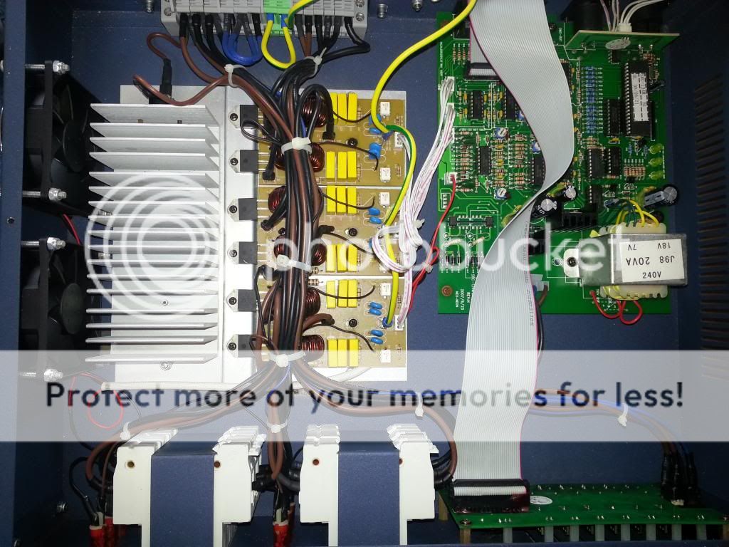 Thanks!
|
|
 |
|
|
shagnasty
Old Croc
Joined: 30 July 2007 Location: Guildford, UK Status: Offline Points: 7683 |
Post Options
Thanks(0)
Quote Reply
Posted: 10 April 2013 at 1:54pm |
|
If I was a gambling man I'd have a tenner it is one of these babies gone :-
 Tricky to be more precise as i would need to trace the wire to MCB 1 to work out which triac it is.. Prob a BTA 8amp device, replace it with the higest ampere rated one in teh same package, make sure the letters are teh same as that is your gate sensitivity and you need it to still work....
|
|
|
|
|
Stray-Sounds
Old Croc
Joined: 13 March 2008 Location: Wales Status: Offline Points: 2426 |
Post Options
Thanks(0)
Quote Reply
Posted: 10 April 2013 at 2:00pm |
|
You've lost me!
CH1 is the nearest of the 3 boards, not sure which side though. I'm thinking this is probably something I will need to have looked at by a pro!
|
|
|
|
|
shagnasty
Old Croc
Joined: 30 July 2007 Location: Guildford, UK Status: Offline Points: 7683 |
Post Options
Thanks(0)
Quote Reply
Posted: 10 April 2013 at 2:14pm |
|
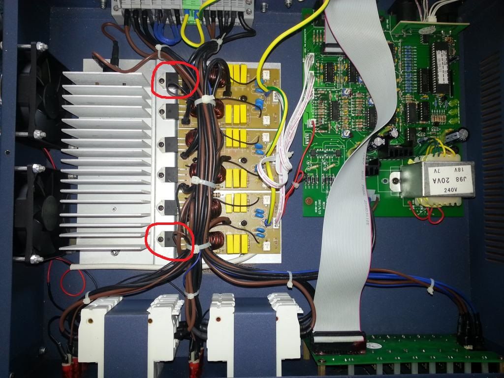
Then the triac is the black thing in the red circle, read the numbers off it, order one from CPC, Farnell, RS or Maplin.
Undo the screw, cut the 3 legs off the old one about where I've put the red lines  and then simple screw the new one down with a blob of thermal paste, overlap the legs with the old ones by a couple of mm and solder them. Reapired and you haven't even lifted the PCB of de-soldered anything!!!  |
|
|
|
|
Stray-Sounds
Old Croc
Joined: 13 March 2008 Location: Wales Status: Offline Points: 2426 |
Post Options
Thanks(0)
Quote Reply
Posted: 10 April 2013 at 3:17pm |
|
Ahh very nice!
I Didn't really know what I was looking for but I tested each possible combination on every triac and got the same readings so I thought that they must be OK?! Is there a way of testing them? Thanks
|
|
|
|
|
shagnasty
Old Croc
Joined: 30 July 2007 Location: Guildford, UK Status: Offline Points: 7683 |
Post Options
Thanks(0)
Quote Reply
Posted: 10 April 2013 at 4:36pm |
|
you can, find the pinout and measure resistance between A1 and A2, I think you'll find it is lower on ch1 than the others.
The little white 6 pin devices are opto isolators, they will be wired via a gate protection resistor, if you desolder one end of the resistor the channel won't come on if the triac is working, if the triac has blown, which they do it will stay on.... |
|
|
|
|
Stray-Sounds
Old Croc
Joined: 13 March 2008 Location: Wales Status: Offline Points: 2426 |
Post Options
Thanks(0)
Quote Reply
Posted: 10 April 2013 at 6:17pm |
|
I'm afraid none of this makes much sense to me! What/where are A1 and A2?
Thanks!
|
|
|
|
|
GregM
Young Croc 
Joined: 13 December 2009 Location: NE Hampshire Status: Offline Points: 525 |
Post Options
Thanks(0)
Quote Reply
Posted: 10 April 2013 at 8:23pm |
Edited by GregM - 10 April 2013 at 8:24pm |
|
|
Remember, if you don't want to hear the answer, don't ask the question!
|
|
|
|
|
shagnasty
Old Croc
Joined: 30 July 2007 Location: Guildford, UK Status: Offline Points: 7683 |
Post Options
Thanks(0)
Quote Reply
Posted: 10 April 2013 at 11:40pm |
|
you need to read off the device ID and get the pin out, it will be something like this :-
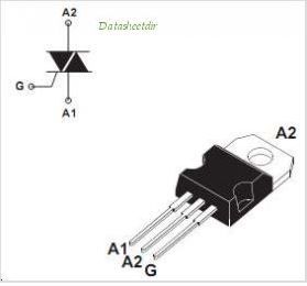 that one is a BTB device and does have an isolated tab, I would guess yours are BTA devices which do, if they don't be carefull to not damage to insulator kit on the tab abd screw. once you have the pinout you can work out which is the gate, TBH, I'd prob just snip the gate leg with a fine pair of cutters, if the channel is still on you have a blown triac, if that takes the channel off you have blown opto triac or a logic issue, that is a more involved repair.... |
|
|
|
|
Stray-Sounds
Old Croc
Joined: 13 March 2008 Location: Wales Status: Offline Points: 2426 |
Post Options
Thanks(0)
Quote Reply
Posted: 11 April 2013 at 12:35am |
|
Mine are BTA41 600B. A1, A1 and G seem to be the same as in the image you posted. I will try what you suggested tomorrow! Many thanks :)
|
|
|
|
|
Richthelightningguy
Registered User 

Joined: 27 January 2012 Location: Lincoln Status: Offline Points: 51 |
Post Options
Thanks(0)
Quote Reply
Posted: 11 April 2013 at 7:36am |
|
yup sounds like a tri-ac cheap and easy to replace you might need a magnifying glass to get numbers from originals e.bay for parts get a few for spares . a steady hand on the soldering iron helps as well
|
|
|
WITHOUT LIGHTS ITS JUST RADIO
|
|
|
|
|
shagnasty
Old Croc
Joined: 30 July 2007 Location: Guildford, UK Status: Offline Points: 7683 |
Post Options
Thanks(0)
Quote Reply
Posted: 11 April 2013 at 9:17am |
|
A BTA 41 is isolated tab, and a pretty decent spec device, easy to get hold of too!!!
|
|
|
|
|
Post Reply
|
Page 12> |
| Tweet |
| Forum Jump | Forum Permissions You cannot post new topics in this forum You cannot reply to topics in this forum You cannot delete your posts in this forum You cannot edit your posts in this forum You cannot create polls in this forum You cannot vote in polls in this forum |


 Topic Options
 shagnasty wrote: