
|
Signal chain overload effects |
Post Reply 
|
Page 123 6> |
| Author | ||
audiomik 
Old Croc 

Joined: 06 April 2010 Location: Bath, UK Status: Offline Points: 2956 |
 Post Options Post Options
") Thanks(0) Thanks(0)
 Quote Reply Quote Reply
 Topic: Signal chain overload effects Topic: Signal chain overload effectsPosted: 04 February 2012 at 8:25am |
|
|
Thread branched from: Mixer for DJ use to look into the effects of overload distortion products created in the signal path as opposed to Amplifier output clipping.
To start with, I will be posting up results, as they become available, for a Mixer input Overloaded with 2 tone sources to review the effects of distortion products appearing in the full bandwidth of the final signal chain output of an Amplifier run below it's rated output. Test subjects are a Cloud CX132 feeding a Matrx XT500 to start with. Mik |
||
|
Warning! May contain Nuts
plus springs, washers, screws, etc, etc. |
||
 |
||
|
audiomik
Old Croc
Joined: 06 April 2010 Location: Bath, UK Status: Offline Points: 2956 |
Post Options
Thanks(0)
Quote Reply
Posted: 04 February 2012 at 9:54am |
|
|
First set of results for the Mixer/Amplifier combination showing a 'normal' input level and an overloaded input:
Firstly a two tone signal applied to the Mixer Input at a level so as not to overload the Input and monitored at the Amplifier output:  A spectrum analysis of this signal below:  Now with the input gain of the Cloud increased to maximum so as to overload the input stage; the Output waveform of the Amplifier is:  and the Spectrum of this composite 2 tone signal generates this: 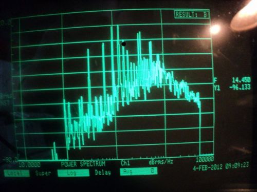 It can be seen that there are a substantial number of artifacts compared with the non-overloaded input signal both as a result of the clipping and intermodulation products. The test frequencies used are 960 and 1120Hz and the measured Amplifier output was of the order of 5V rms. As to how much additional energy is passed to a 'speaker by the 'overload signal' compared with the base-line one, the Spectrum Analyser results show a substantial difference. Mik |
||
|
Warning! May contain Nuts
plus springs, washers, screws, etc, etc. |
||
|
||
|
audiomik
Old Croc
Joined: 06 April 2010 Location: Bath, UK Status: Offline Points: 2956 |
Post Options
Thanks(0)
Quote Reply
Posted: 04 February 2012 at 10:29am |
|
|
As the other thread asked for having an LMS in line, results below for the same test conditions as above but with a 1kHz LR High Pass filter using a LEM DX24:
firstly the spectrum of the output for the normal level signal:  and for the input overloaded signal:  Both were at an output level for the Amplifier of 5V RMS. Mik |
||
|
Warning! May contain Nuts
plus springs, washers, screws, etc, etc. |
||
|
||
|
Muckerbarnes1
Old Croc

Joined: 20 March 2010 Location: Stroud Status: Offline Points: 2637 |
Post Options
Thanks(0)
Quote Reply
Posted: 04 February 2012 at 11:23am |
|
|
What is the normal and overloaded signal input level Mik?
|
||
|
Billy Dawg.
|
||
|
||
|
audiomik
Old Croc
Joined: 06 April 2010 Location: Bath, UK Status: Offline Points: 2956 |
Post Options
Thanks(0)
Quote Reply
Posted: 04 February 2012 at 11:38am |
|
|
Input level at 4V RMS to the Cloud, input gain adjusted to max for the 'overload state' and reduced for the 'non overload' state to minimum.
Zone level control then adjusted for 5V output from the Amplifier. With the DX24 in circuit, Zone level again adjusted for the same Amplifier Output to compensate for the filtering. Key thing here is that the increase in 'energy', from signal path overload, which is applied to the Load on the Amplifier is independent of the Amplifier clip point, a significant issue when using larger power output Amplifiers than driver ratings. Refers to running mixers 'into the red' for those who haven't read the thread which this follows on from.......... Mik |
||
|
Warning! May contain Nuts
plus springs, washers, screws, etc, etc. |
||
|
||
|
Earplug
Old Croc
Joined: 03 January 2012 Location: Europe Status: Offline Points: 7752 |
Post Options
Thanks(0)
Quote Reply
Posted: 04 February 2012 at 1:47pm |
|
|
Thanks for starting this thread- and the photos. I ran a few (quick) tests the other day with a Berry DCX2496 and must say that the output waveforms were a lot better than from the xover I used for my initial tests. I never had time to take any photos, but will. I´ve also got a couple of BSS FDS-360´s so I´ll test those and post some photos as well.
Edited by Earplug - 04 February 2012 at 1:48pm |
||
|
Earplugs Are For Wimps!
|
||
|
||
|
norty303
Old Croc

Joined: 18 August 2004 Location: Eastbourne Status: Offline Points: 8800 |
Post Options
Thanks(0)
Quote Reply
Posted: 04 February 2012 at 7:30pm |
|
Could they be using a 'read ahead' delay like for limiters? |
||
|
My laser stuff: Frikkin Lasers
|
||
|
||
|
audiomik
Old Croc
Joined: 06 April 2010 Location: Bath, UK Status: Offline Points: 2956 |
Post Options
Thanks(0)
Quote Reply
Posted: 04 February 2012 at 8:53pm |
|
|
The Berry DCX2496 uses the Analog Devices ADSP-21065L DSP IC for it's processing, the data sheet for this plus the source code for it's firmware is available here.
If you look into the source code instruction set for the firmware then your question relating to 'read ahead' will no doubt be answered... Mik |
||
|
Warning! May contain Nuts
plus springs, washers, screws, etc, etc. |
||
|
||
|
Earplug
Old Croc
Joined: 03 January 2012 Location: Europe Status: Offline Points: 7752 |
Post Options
Thanks(0)
Quote Reply
Posted: 05 February 2012 at 1:51pm |
|
Ok, had another look today - both the DCX and a BSS 360. The other day I didn´t run the square wave into the DCX, just checked on it´s response to overloading, ie how well it´s limiters worked and they did ok. Today I did the square wave tests and there wasn´t much difference between the o/p of the BSS and the DCX. 60Hz, 2,5V square: BSS, Low Out:  Mid Out:  Top Out:  Sorry about the bad pic, but we see that there´s still harmonics getting through from a 60Hz, square! Now 600Hz: BSS Mid Out:  Top Out: 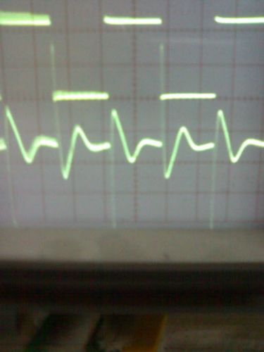 Now the DCX: 60Hz, Low Out:  Mid Out:  600Hz, Mid Out:  Top Out:  I haven´t checked on how the DCX actually works, but if it is FIR....  |
||
|
Earplugs Are For Wimps!
|
||
|
||
|
audiomik
Old Croc
Joined: 06 April 2010 Location: Bath, UK Status: Offline Points: 2956 |
Post Options
Thanks(0)
Quote Reply
Posted: 05 February 2012 at 3:06pm |
|
|
Earplug
interesting results, will look at repeating your test method here. What are your DSP Filter settings? Think that Latency tests* are needed so have just switched on my bench to get the instruments 'warmed up' - takes a couple of hours for all to stabilise properly Mik *Think I can see some phase differences at the leading edges of your 'scope images which may be a result of either Latency in the DSP or Filter characteristics. |
||
|
Warning! May contain Nuts
plus springs, washers, screws, etc, etc. |
||
|
||
|
Earplug
Old Croc
Joined: 03 January 2012 Location: Europe Status: Offline Points: 7752 |
Post Options
Thanks(0)
Quote Reply
Posted: 05 February 2012 at 3:39pm |
|
|
Ok.
Do you mean the BSS plots, that are obviously out of phase?  The bloody thing runs on pin 3 hot and my jack to xlr are all pin 2 hot, therefore.... My DSP settings are: Low: 20Hz - 100Hz Mid: 100Hz - 2k07Hz Top: 2k07 - 18kHz All filters BUT24 On the DCX, I´m pretty sure that the traces lined up ok with a simple sin wave, but can check that again later - let you know. In any case, I imagine that severe distortion - ie a square wave, would introduce phase shifts along with all the other stuff we see above. I´d love to see the results from a driverack or omnidrive, etc. Anyway, looking forward to your results! Edited by Earplug - 05 February 2012 at 3:41pm |
||
|
Earplugs Are For Wimps!
|
||
|
||
|
audiomik
Old Croc
Joined: 06 April 2010 Location: Bath, UK Status: Offline Points: 2956 |
Post Options
Thanks(0)
Quote Reply
Posted: 05 February 2012 at 4:26pm |
|
|
OK, initial tests using same setup as before with a 1kHz HP LR Filter setting for the LEM:
Squarewave at 1kHz input with the Amplifier output in the centre of the screen:  And the output spectrum of the filter:  Measurement Error: Next an expanded timebase of 0.1mS/div to look closely at the time difference of the zero crossing point of the output compared with the input signal to assess latency.  OK,  - a fundamental error in measuring the Latency by using the 1kHz square wave input which obscured a 1mS difference from the real value of this timing difference as it appeared on the next cycle of the waveform. - a fundamental error in measuring the Latency by using the 1kHz square wave input which obscured a 1mS difference from the real value of this timing difference as it appeared on the next cycle of the waveform.Corrected in the 'scope image below, using a 100Hz square wave and 1mS/div timebase, which shows a more realistic figure of 1.2mS for the delay between input and Hi-Pass output of the test setup:  Mik Edit 1: add timebase value Edit 2: add corrected latency measurement due to timing error Edited by audiomik - 06 February 2012 at 2:42am |
||
|
Warning! May contain Nuts
plus springs, washers, screws, etc, etc. |
||
|
||
|
Post Reply
|
Page 123 6> |
| Tweet |
| Forum Jump | Forum Permissions You cannot post new topics in this forum You cannot reply to topics in this forum You cannot delete your posts in this forum You cannot edit your posts in this forum You cannot create polls in this forum You cannot vote in polls in this forum |


 Topic Options
 I ran a few (quick) tests the other day with a Berry DCX2496 and must say that the output waveforms were a lot better than from the xover I used for my initial tests.