
|
Dual 18" sub idea |
Post Reply 
|
Page 12> |
| Author | |
FOO 
Young Croc 

Joined: 23 December 2018 Location: Denmark Status: Online Points: 951 |
 Post Options Post Options
") Thanks(0) Thanks(0)
 Quote Reply Quote Reply
 Topic: Dual 18" sub idea Topic: Dual 18" sub ideaPosted: 06 March 2024 at 8:49pm |
|
Hello everybody
I am toying with an idea about a low profiled dual 18" ported sub. But i am a bit in the woods about how i should sim it. Please have a look at the pictures... Is it a bandpass type or just straight-up ported box? I am also thinking of ditchin´the outside port and go for a slot port that ends behind the woofers instead of infront of the woofers. The ported chamber will have around 360 liters internal volume.  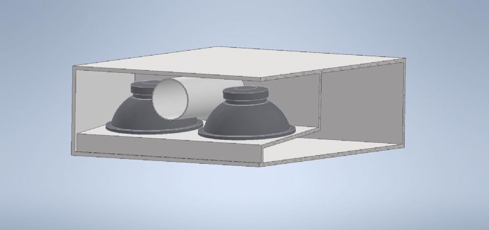 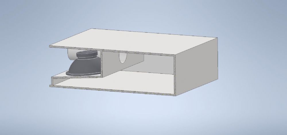 |
|
 |
|
|
smitske96
Young Croc
Joined: 16 February 2016 Location: The Netherlands Status: Offline Points: 1217 |
Post Options
Thanks(0)
Quote Reply
Posted: 06 March 2024 at 9:26pm |
|
I would sim it as an offset driver horn. What are you aiming at as minimum height?
|
|
|
|
|
RoadRunnersDust
Young Croc

Joined: 03 December 2013 Location: United Kingdom Status: Offline Points: 617 |
Post Options
Thanks(0)
Quote Reply
Posted: 06 March 2024 at 11:32pm |
|
Looks like a 6th order bandpass not dissimilar to EV Manifold bins
Not sure what about it you would sim as a horn, the only significantly tapered section feeds into the rear chamber so would just act as rear chamber volume and isn’t long enough on the “outside” to provide any real horn loading effect
|
|
|
|
|
FOO
Young Croc
Joined: 23 December 2018 Location: Denmark Status: Online Points: 951 |
Post Options
Thanks(0)
Quote Reply
Posted: 07 March 2024 at 5:02am |
|
It can't be higher than 44cm, So I am aiming for 42cm. width and depth can be whatever I want, but at this size I can fit three enclosures side by side.
I would just sim it as ported if the baffle was tilted less to around 45 degress. But this is 82,5 degress so very close to EV MT2 manifold as you point out Roadrunner. I haven't picked out a driver yet, but I recon I would be needing a very strong cone and suspension. Something the EV MT2 didn't have.
|
|
|
|
|
smitske96
Young Croc
Joined: 16 February 2016 Location: The Netherlands Status: Offline Points: 1217 |
Post Options
Thanks(0)
Quote Reply
Posted: 07 March 2024 at 9:45am |
Why would it need to be tapered to act like a horn? Its easier (and probably more truthfull to practise) to simulate it as a 2 segment ODH. You will definately see gain from it (being usable is another story). By just looking at you drawing and doing some gueswork I simmed the following:  And simmed as a standard BR:  While tuning is really low due to the small port area and relative long lenght, I can say that the real life response of the cab is more in line with the first sim. It acts like a large resonator (comparable to the paraflex high tuned resonator) and adds quite some gain higher up. How would you sim it as a 6th order bandpass? How would you specify that chamber? I would say in real life its a bit between the two sims eventually, the gain from the cavity is imho not small enough to just ignore it.
|
|
|
|
|
VECTORDJ
Young Croc

Joined: 11 June 2006 Location: United States Status: Offline Points: 585 |
Post Options
Thanks(0)
Quote Reply
Posted: 07 March 2024 at 10:11am |
|
You reinvented an old EV design idea (and others)....It is almost impossible to come up with a NEW Speaker Box Design....Look how many times the Turbosound and Cervin Vega Bass Bins have been copied in the Forums...It is cool to copy CV or JBL's 18-W ideas..Done it Myself many times but I did not claim it was a NEW Design....VECTORSONICS
|
|
|
|
|
RoadRunnersDust
Young Croc
Joined: 03 December 2013 Location: United Kingdom Status: Offline Points: 617 |
Post Options
Thanks(0)
Quote Reply
Posted: 07 March 2024 at 11:49am |
Because that is fundamentally the difference between a horn and a port? Without providing any actual horn loading it is just a resonator. Did you model the front chamber area on that BR plot?
|
|
|
|
|
smitske96
Young Croc
Joined: 16 February 2016 Location: The Netherlands Status: Offline Points: 1217 |
Post Options
Thanks(0)
Quote Reply
Posted: 07 March 2024 at 12:46pm |
|
From what amount of taper does it qualify as a horn? The qualification of it does not matter for a program like hornresp. So again, how would you sim it?
Edited by smitske96 - 07 March 2024 at 12:48pm |
|
|
|
|
RoadRunnersDust
Young Croc
Joined: 03 December 2013 Location: United Kingdom Status: Offline Points: 617 |
Post Options
Thanks(0)
Quote Reply
Posted: 07 March 2024 at 2:05pm |
|
Easiest way to sim it would be as a vented rear chamber + a front chamber either using S1-S2 or the front chamber entry in the the section below driver specs.
It’s too short and the CSA too large for the drivers being mounted flat to effect it beyond the margin of error of a HR sim
|
|
|
|
|
FOO
Young Croc
Joined: 23 December 2018 Location: Denmark Status: Online Points: 951 |
Post Options
Thanks(0)
Quote Reply
Posted: 07 March 2024 at 9:17pm |
|
I have been reading your inputs on this and at the same time doing some more measuring of the location the enclosures need to fit in.
It is possible to make them wider without causing to much hazzle when deploying them at the venue, so i think i have come up with a more simple and at the same time a bit cheaper design to build.  Outside dim: 1236mm wide, 1400mm deep and 425mm high. Baffle slanted at 35 degrees from horizontal. Two slot ports. Each 110x189mm. Minimum depth need to be 590mm de clear the baffle. Total internal volume around 440-445 liters when bracing, handles etc. etc. are all accounted for. Note that the depth of the enclosure isnt fixed. There is plenty of space behind where the enclosures will be positioned. Would this design fit under a BR type design? it almost as close as it can be. I guess two enclosures would do the trick, but if this current width is enough it is possible to fit a third enclosure. Headroom is nice to have  As a start i will be aiming for 18sound 18LW2400 as it is cheap to replace and does a good job. Proven and reliable. Mind you that this is only a rought idea. Fine tuning will be the next step so the enclosure will be made to fit the driver of my choice.
|
|
|
|
|
RoadRunnersDust
Young Croc
Joined: 03 December 2013 Location: United Kingdom Status: Offline Points: 617 |
Post Options
Thanks(0)
Quote Reply
Posted: 07 March 2024 at 10:13pm |
|
The smaller you make that “front chamber” where the drivers are mounted the less significant you make any acoustic effect it has (especially at low frequencies). With that latest revision I think you’ll be totally safe to model it just as a BR, especially with the drivers facing upwards.
One thing you might consider to protect the drivers from drinks, etc. it to mount them the other way up, at that point the floor may cause a boundary effect that you need to consider in conjunction with the little chamber as the boundary will artificially increase the size of that chamber. Likewise boundary and inter-box coupling of the slot ports may be something to consider, depending on how anal you intend to get with this design.
Be careful about how much volume you will end up consuming in the cabinet with bracing when making your volume calculations at this stage. Especially as it is going to be mounted under a stage, you want it to be as solid as possible. |
|
|
|
|
MarjanM
Old Croc 

Joined: 10 February 2005 Location: Macedonia Status: Offline Points: 7844 |
Post Options
Thanks(0)
Quote Reply
Posted: 09 March 2024 at 4:14pm |
|
Why not 15s then?
|
|
|
Marjan Milosevic
MM-Acoustics www.mm-acoustics.com https://www.facebook.com/pages/MM-Acoustics/608901282527713 |
|
|
|
|
Post Reply
|
Page 12> |
| Tweet |
| Forum Jump | Forum Permissions You cannot post new topics in this forum You cannot reply to topics in this forum You cannot delete your posts in this forum You cannot edit your posts in this forum You cannot create polls in this forum You cannot vote in polls in this forum |


 Topic Options
 RoadRunnersDust wrote: