
|
Haze Caravelle (barn find!) |
Post Reply 
|
Page <1234 6> |
| Author | |
vital spark 
Registered User 
Joined: 16 November 2018 Status: Offline Points: 36 |
 Post Options Post Options
") Thanks(0) Thanks(0)
 Quote Reply Quote Reply
 Posted: 20 November 2018 at 10:39am Posted: 20 November 2018 at 10:39am |
Transformers look the same, but they arent unfortunately. I'll do a proper diagram later, but the one on the right is as follows (as i remember it): 240v ac to the transformer input, Ov and 30v used on the secondary, through the bridge rectifier at 30v DC and on to the two caps. line voltage at the input fuse terminals 87v DC Left: 240v ac transformer primary. Transformer secondary +30/-30v tappings. Centre tapped to caps/earth. AC voltage at bridge rectifier 60v, line voltage at the input fuse terminals 87v DC.
|
|
 |
|
|
vital spark
Registered User
Joined: 16 November 2018 Status: Offline Points: 36 |
Post Options
Thanks(0)
Quote Reply
Posted: 27 November 2018 at 9:23am |
|
Good Morning.
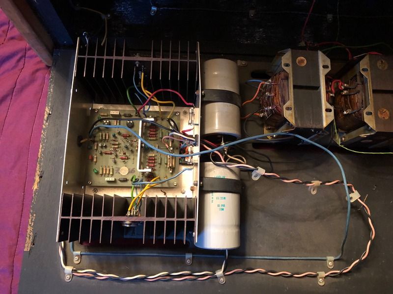
A bit of progress being made. All powered up, and the mixer seems to be mostly working fine. Only really the second mic input has a proper issue, and will investigate later. Looking into the amps, and wired up the right hand amp again, and found its output weak and sounding pretty bad. Definately the amp itself. Cant see any dry joints, fried components or broken tracks, but what i can see from voltage testing, is that one of the power transistors show 44v to its opposite DC line, where all the others (both amps) have 87v DC, so with my basic knowledge, i'm assuming i have a duff power transistor!? 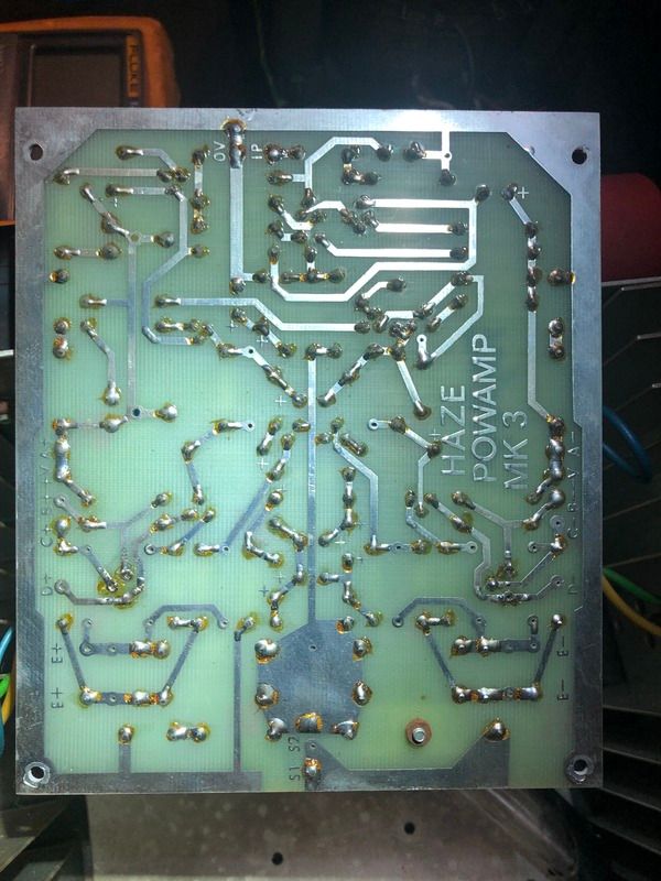 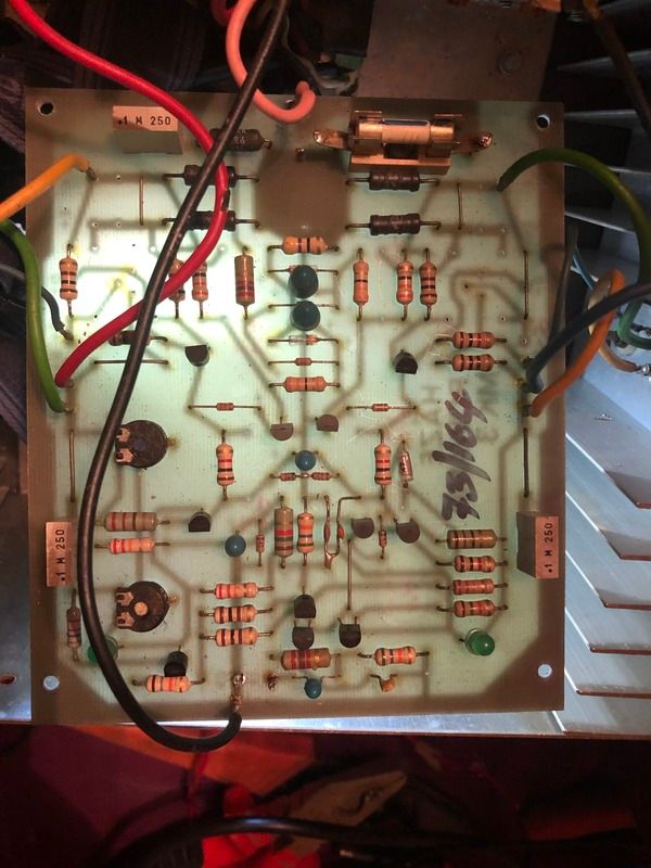 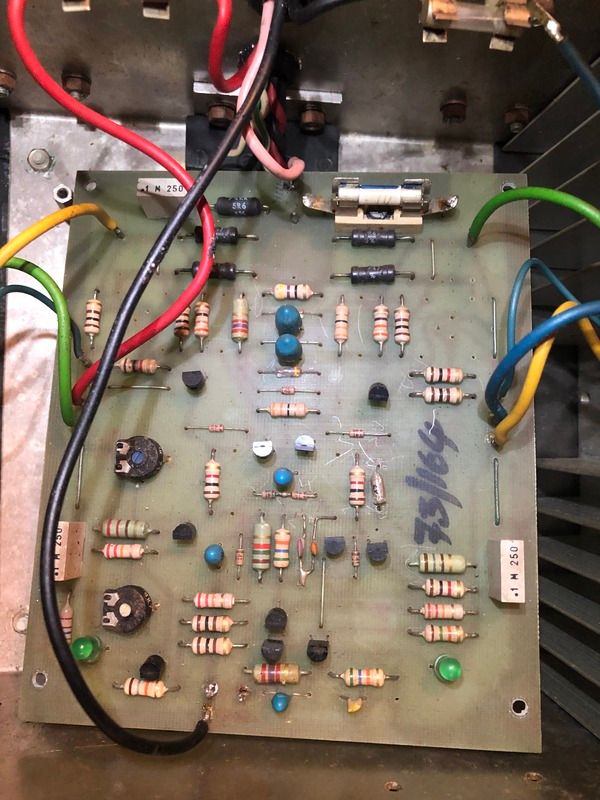  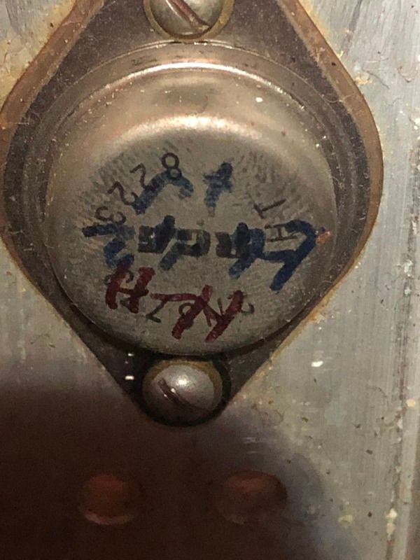 Edited by vital spark - 27 November 2018 at 9:24am |
|
|
|
|
concept-10
Young Croc 
Joined: 17 May 2016 Status: Offline Points: 1293 |
Post Options
Thanks(1)
Quote Reply
Posted: 27 November 2018 at 9:56am |
|
Loving this thread

|
|
|
|
|
vital spark
Registered User
Joined: 16 November 2018 Status: Offline Points: 36 |
Post Options
Thanks(0)
Quote Reply
Posted: 27 November 2018 at 2:45pm |
Same with the power transistors, all the board mounted ones tested ok for resistance and direction. I'm not an expert by any stretch, and my fault finding is merely by comparison. If i voltage test again, would comparison be useful again (ie, all pretty much showing the same voltages each), or do you have any more tips for testing? For all the cost, i might just be as well replacing all of them though? Thanks for the help, Al
|
|
|
|
|
APW
Young Croc

Joined: 13 November 2012 Location: Kent, UK Status: Offline Points: 1174 |
Post Options
Thanks(0)
Quote Reply
Posted: 27 November 2018 at 4:33pm |
|
that amp appears to missing its driver transistors.
|
|
|
|
|
odc04r
Old Croc 

Joined: 12 July 2006 Location: Sarfampton Status: Offline Points: 5482 |
Post Options
Thanks(0)
Quote Reply
Posted: 27 November 2018 at 4:56pm |
|
Yes they certainly are missing, you can see on the underside that there has been rework around where they should be. Getting originals might be difficult even if you knew what to go for. This is the kind of thing you might get some good help for on diyaudio.com If you could spend some time tracing out and drawing the circuit people there would probably tell you exactly what to substitute in. |
|
|
|
|
jbl_man
Moderator Group 
Joined: 12 January 2005 Location: London. Status: Offline Points: 11155 |
Post Options
Thanks(0)
Quote Reply
Posted: 27 November 2018 at 6:15pm |
|
Follow the circuit back,and see what is fitted on the other (working) amp PCB as drivers. Should be able to get a transistor number from the working one.
|
|
|
Be seeing you.
|
|
|
|
|
jbl_man
Moderator Group
Joined: 12 January 2005 Location: London. Status: Offline Points: 11155 |
Post Options
Thanks(0)
Quote Reply
Posted: 27 November 2018 at 8:39pm |
|
It will be the two that are mounted on the alluminium strip in the middle.
 |
|
|
Be seeing you.
|
|
|
|
|
vital spark
Registered User
Joined: 16 November 2018 Status: Offline Points: 36 |
Post Options
Thanks(0)
Quote Reply
Posted: 28 November 2018 at 8:37am |
|
interesting stuff and thanks for your input. I did notice the potential missing transistors, but dismissed it, due to the fact there are other differences, such as the left amp has 4 power transistors, and other subtle differences, such as more resistors, and some other additional components connected to the heat sink.
Main thing is, both PCB's and enclosures are identical (Haze POWAMP MK3). Question is, do i fit the two missing transistors and heatsink only, or change the right amp to match exactly the left (add 2 more power transistors), or a 3rd option which would help greatly with my OCD, which is to change the caps and tranny's also so they match. Third option might be deemed as sacralidge, since it would likely be torroidal transformers, and 21st century caps? Whats your thoughts guys? Job is growing slightly, but not outwith the realms of my capability, and i'm all for doing it right (and once only!)
|
|
|
|
|
jbl_man
Moderator Group
Joined: 12 January 2005 Location: London. Status: Offline Points: 11155 |
Post Options
Thanks(1)
Quote Reply
Posted: 28 November 2018 at 9:28am |
|
First thing would be to get the number off the existing driver transistors,and see if they (or an equivilant) are still available.
|
|
|
Be seeing you.
|
|
|
|
|
odc04r
Old Croc
Joined: 12 July 2006 Location: Sarfampton Status: Offline Points: 5482 |
Post Options
Thanks(1)
Quote Reply
Posted: 28 November 2018 at 12:31pm |
|
Yep, follow the priorities. Also check to see if you can find spare power transistors for the missing slots. Beware of sales on eBay etc of harder to find devices, transistor fakes are rife if there is a profit to be made reprinting cheaper devices to pass off as older/rarer/more expensive. Power transistors are especially bad for this. Personally I would draw out the circuits, figure them out and then substitute sensible modern components as required/necessary to bring them back to life. I'd definitely replace electrolytic caps, but I'd leave the small signal components alone if they tested well. For me vintage kit is 99% the outside appearence physical functionality. I have no problem making sensible modern part swaps as necessary to amplifier modules and PSUs etc. Appreciate that other peoples opinion can differ.
|
|
|
|
|
vital spark
Registered User
Joined: 16 November 2018 Status: Offline Points: 36 |
Post Options
Thanks(0)
Quote Reply
Posted: 28 November 2018 at 12:52pm |
|
Those transistors are TIP41C's, and it looks like its readily available from a quick google.
Will definately draw out both circuit diagrams and take it from there. Thanks for your input/opinions/advice so far. it's really appreciated. My concern is that the differences between the two amps is to accommodate additional power transistors, possible a higher rated amp, so in my limited opinion, it makes sense to replicate the working amp with the same components, rather than take a stab in the dark as to how the non working one should be. Al |
|
|
|
|
Post Reply
|
Page <1234 6> |
| Tweet |
| Forum Jump | Forum Permissions You cannot post new topics in this forum You cannot reply to topics in this forum You cannot delete your posts in this forum You cannot edit your posts in this forum You cannot create polls in this forum You cannot vote in polls in this forum |


")


 Topic Options
 jbl_man wrote: