
|
Haze Caravelle (barn find!) |
Post Reply 
|
Page <12345 6> |
| Author | |
kedwardsleisure 
Old Croc 
Joined: 20 January 2009 Location: Staffordshire Status: Offline Points: 4949 |
 Post Options Post Options
") Thanks(0) Thanks(0)
 Quote Reply Quote Reply
 Posted: 28 November 2018 at 4:23pm Posted: 28 November 2018 at 4:23pm |
|
are those resistors burnt out by the fuse?
|
|
|
Kevin
North Staffordshire |
|
 |
|
|
odc04r
Old Croc

Joined: 12 July 2006 Location: Sarfampton Status: Offline Points: 5482 |
Post Options
Thanks(0)
Quote Reply
Posted: 29 November 2018 at 9:51am |
|
I thought possible the same, but after zooming in the markings are legible. I think for whatever reason they are just black resistors. If you draw out the circuit and indicate components then post it up here+DIYAudio you will end up with many suggestions regarding circuit improvements/stability/ability to drive the putput stage etc. Driving a pair of output transistors should not be an issue for a single driver but some attention may have to be paid to heatsinking/bias. Edited by odc04r - 29 November 2018 at 9:52am |
|
|
|
|
Pinyorouk
Young Croc 
Joined: 31 January 2011 Status: Offline Points: 551 |
Post Options
Thanks(0)
Quote Reply
Posted: 29 November 2018 at 3:44pm |
|
Usaually if there are 2 output transtors it is only good for 8 ohm operation minimum. With 4 output transistors, 4 ohm operation minimum. That was the case with amps I worked on in the 80's.
Edited by Pinyorouk - 29 November 2018 at 4:45pm |
|
|
|
|
vital spark
Registered User 
Joined: 16 November 2018 Status: Offline Points: 36 |
Post Options
Thanks(0)
Quote Reply
Posted: 29 November 2018 at 10:29pm |
|
hi, I actually thought the same about those resistors, since there’s a little heat damage against the fuse. I removed them and tested individually. They are resistors, and a bit of searching their part numbers etc and they are 0.47 ohm fused resistors. Very low resistance, so assume they are effectively just a fuse?
Progressing along with the rest. I’m 50% there with a circuit diagram on the first, and with the milder weather I’m finishing painting the transit case. Also lost two starboard side tyres commuting tonight, to a pothole, so that’s a bit of a setback! Edited by vital spark - 29 November 2018 at 10:33pm |
|
|
|
|
odc04r
Old Croc
Joined: 12 July 2006 Location: Sarfampton Status: Offline Points: 5482 |
Post Options
Thanks(0)
Quote Reply
Posted: 30 November 2018 at 11:48am |
They're possibly both fuses and also act as emitter balancing resistors when using multiple output transistors to make sure currents stay roughly balanced. Good work on the diagram, be interested to see it. I'm sure it is a very classic circuit
|
|
|
|
|
Muckerbarnes1
Old Croc

Joined: 20 March 2010 Location: Stroud Status: Offline Points: 2654 |
Post Options
Thanks(1)
Quote Reply
Posted: 14 December 2018 at 9:44am |
|
I fixed lots of these in the late 70's, early 80's.
The same amp modules were in a slave box too. Lots of manufactures made similar. They all used very similar components and are simple to work on. 2 O/P transistors is fine on 4 ohms in such, but that does of course depend on the psu. In general terms 2 2N3773's is 100W and 4 2N3773's is 200W. TIP31/2 and TIP41/2 drivers is very common. I refurb lots of consoles like this.
|
|
|
Billy Dawg.
|
|
|
|
|
vital spark
Registered User
Joined: 16 November 2018 Status: Offline Points: 36 |
Post Options
Thanks(0)
Quote Reply
Posted: 19 December 2018 at 2:40pm |
|
Hi there, i've been quiet, but that means less browsing, more tinkering!
As a general update (and pics to follow), i've finished the transit case, wrapped the unit itself in a faux leather plastic wrap, stripped the bottom door holding the amps, and refurbed, all ready for the rebuild. Completed the schematics and hopefully managed to share my findings below Hopefully i've managed to transfer a PCB into some form of readable schematic. Its tricky trying to keep a schematic with some form of geographical resemblance to a PCB to make it simple to cross ref, but still keep the schematic readable. I'm not an electronics expert by any stretch, so if anything looks odd or cant work, just say! I havent sought any advice regarding any tweaks or upgrades as yet, i'm just keen on getting both working and the same. using the schematics i've ordered the additional/changed components to make both the same as per the "200w" amp. progress/updates: Found some new unused caps of a similar vintage on Ebay (1986). capacitance checks out ok, and probably better than what i had, but not 2018 units. transformers, they do actually seem to be the same units, but a different newer model. Both MT125ft's from the same manufacturer. Also found the secondary wired incorrectly (not centre tapped). the link to combine the two 30v output winding was in the wrong place. the bridge was getting 30vac, and the centre tap was the other 30vac, so possibly explains (without too much thought) why the DC readings were ok, but actually the amp was only using half the secondary winding!? So i've wired them both the same with the correct tapping, and kept them both. De-annodised the heat sinks on the newer amp to make them look the same. Full rewire and tidy up! Also under the amp casings revealed their ages :) more pics to follow! 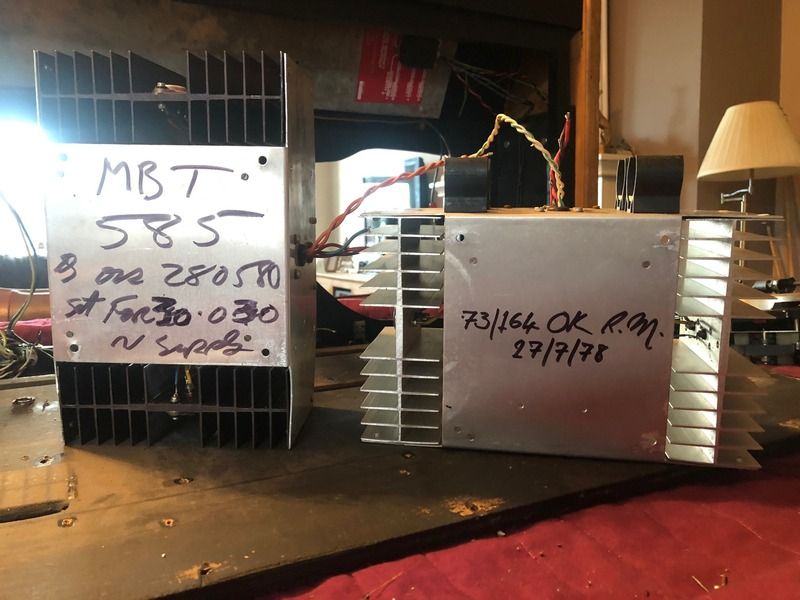 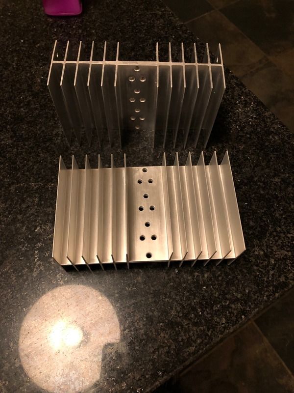 |
|
|
|
|
jbl_man
Moderator Group 
Joined: 12 January 2005 Location: London. Status: Offline Points: 11155 |
Post Options
Thanks(1)
Quote Reply
Posted: 19 December 2018 at 2:57pm |
|
Well done with the schematics.....very interesting, the earlier (non working) amp with the missing parts uses a single 2n3773 on both rails.... wheres the later working one uses two MJ15003 on the + rail, and two MJ15004 on the - rail.
The missing drivers would appear to be TIP42C on the +,and TIP41C on the - side. Edited by jbl_man - 19 December 2018 at 3:00pm |
|
|
Be seeing you.
|
|
|
|
|
vital spark
Registered User
Joined: 16 November 2018 Status: Offline Points: 36 |
Post Options
Thanks(0)
Quote Reply
Posted: 03 January 2019 at 10:42am |
|
Hi all and happy New year.
Well, we had a New Years party, and the old girl performed well. some of the banks get a little hot for my liking, especially since its not running hard, but this is likely due to the biasing not being setup, and i think I've sussed it (found a very good tutorial last night on class AB amps and how they work). 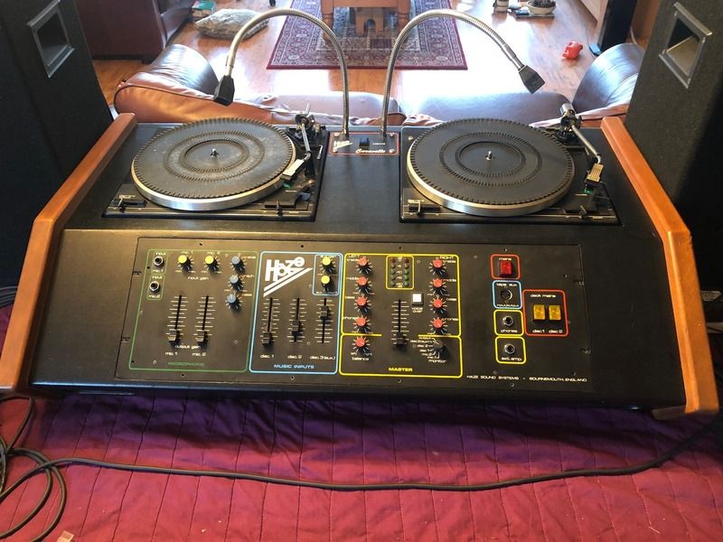 The mixing console has been getting a good workover. some items fixed/ongoing: 1, there's a hum that increases with volume, regardless of what input being used, and its also apparent on the headphone output, so i replaced all the power supply caps. Still present, but at least the caps are now ruled out. - all suggestions appreciated! One of the PSU's has a 15v zenner diode to ground, and i assume its for reverse/overvoltage protection. This was one supply on its own from one transfomer and was red hot to touch. The transformer was putting out 20v, so the diode(and power resitor(see below photo)) were being eating up a lot of energy. I reconfigured the tapping on the transformer to a little over 14v, and all seems to be well. all the slider pots feel nice and smooth with no crackle, so i've left these alone, but most of the rotaries were either tight due to old grease, or crackling, so i went round these and cleaned/lubed and there's now no crackling, however most if not all are just out of spec. the 100k pots range from 120-150k, which is giving some funny effects with the tone controls in particular, where for example, past 100k on the bass pot, and treble dissapears. Managed to find some close alternatives from Farnell, and await their arrival. The knackered mic channel was an easy find. A 714 op amp was hot enough to cook an egg on, so thats replaced and all working. Also received a new deck picked up from Ebay Italy. Rust free, nice smooth tone arm and far less mileage that the one it replaced. The other deck is rusty, the tone arm is far too loose, but otherwise works fine. I'll bide my time and pick up another on Ebay. Both decks treated to an AT95 cartridge, which seems to be working well, but i think might be driving a slightly higher voltage than whatever was fitted previously, or what the console was designed for, since you dont need much gain at all for the deck inputs to be overly loud, and can distort easily and sound a bit tinny at times. Might need to figure out some form of attenuation, or maybe alter the value of the input/loading resistor on the console (currently 46k) Installed a logitech bluetooth audio adaptor into the 3rd deck input, along with an L pad for attenuation. Sounds great/works great and completely stealth :) The lights previously robbed 60v ac from the right hand amp, so i've installed a 5v psu on the main feed and replaced the bulbs. (5v PSU also powers the Bluetooth receiver) Pics below. We'll chuffed with my efforts on rebuilding the right amp, especially considering its working! 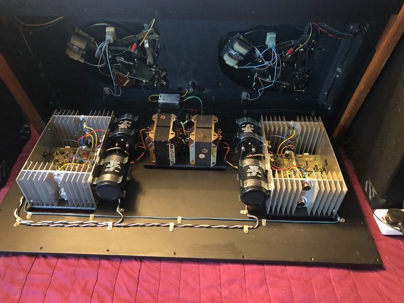 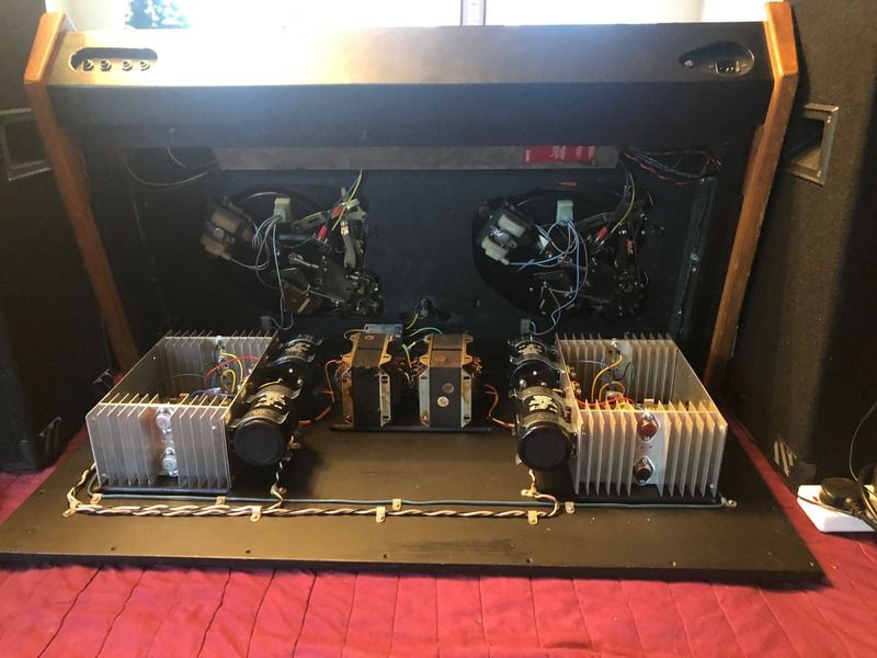 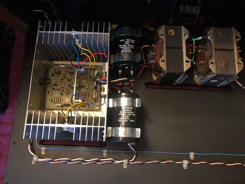 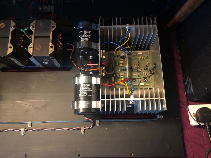 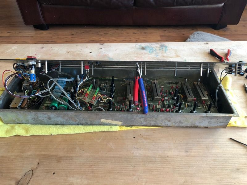 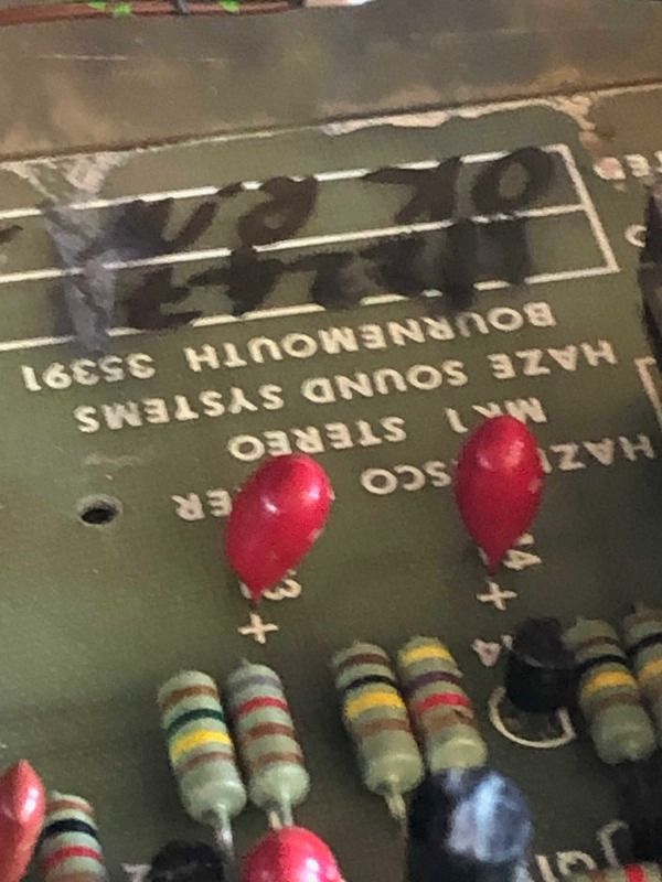 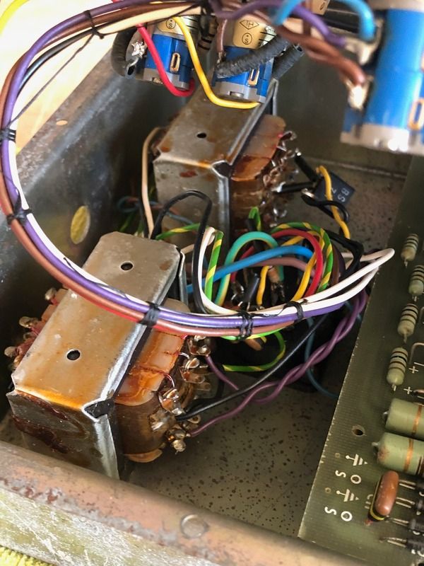 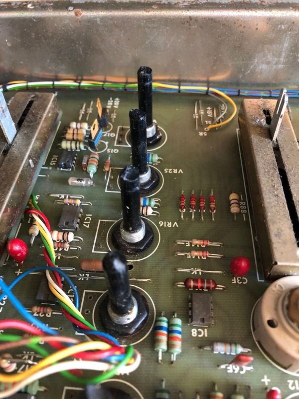 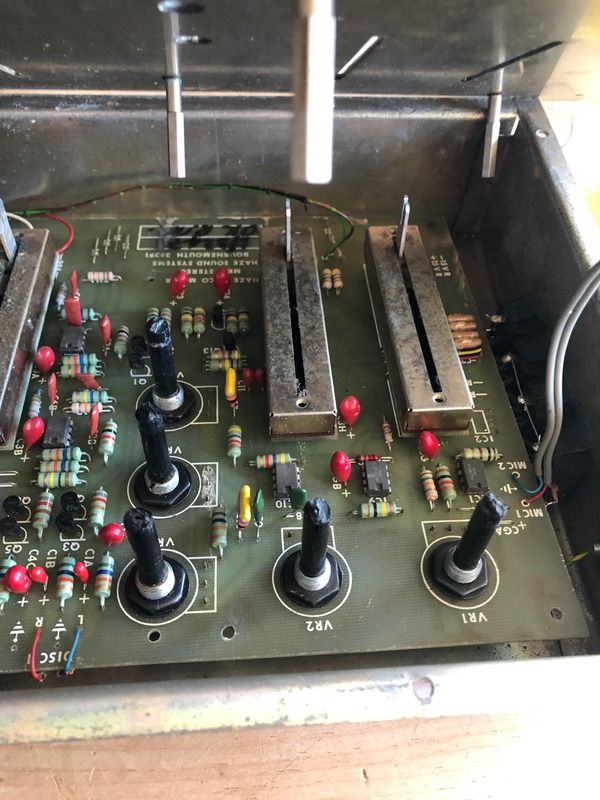 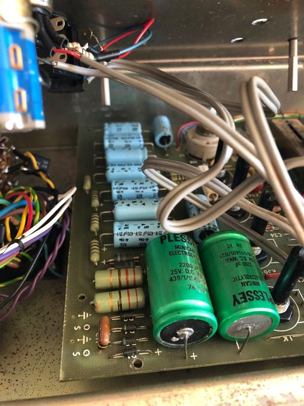 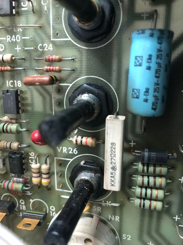 getting there!! |
|
|
|
|
concept-10
Young Croc
Joined: 17 May 2016 Status: Offline Points: 1293 |
Post Options
Thanks(1)
Quote Reply
Posted: 03 January 2019 at 1:47pm |
|
Excellent work, well done

|
|
|
|
|
Robbo
Old Croc
Joined: 05 December 2005 Location: Shropshire Status: Offline Points: 4226 |
Post Options
Thanks(0)
Quote Reply
Posted: 03 January 2019 at 2:11pm |
|
It may be worthwhile fitting an earthed shielding plate across and above the amp modules and mains trannies as they are very close to both the turntables and the mixer when in use.
|
|
|
|
|
vital spark
Registered User
Joined: 16 November 2018 Status: Offline Points: 36 |
Post Options
Thanks(0)
Quote Reply
Posted: 03 January 2019 at 2:41pm |
Robbo, i've thought the same myself. I dont think its the source of my hum though, since theres no difference with the "hood" lifted, or down, but could be from the tranny's to the amps, however from what i can gather, if the hum doesnt vary with the mixer volume, its likely the amps themselves, but the hum does alter with volume. |
|
|
|
|
Post Reply
|
Page <12345 6> |
| Tweet |
| Forum Jump | Forum Permissions You cannot post new topics in this forum You cannot reply to topics in this forum You cannot delete your posts in this forum You cannot edit your posts in this forum You cannot create polls in this forum You cannot vote in polls in this forum |


")


 Topic Options
 vital spark wrote: