
|
2x15" front loaded horn F2B |
Post Reply 
|
Page <1 23456 9> |
| Author | ||||
madboffin 
Old Croc 
Joined: 03 July 2009 Location: Milton Keynes Status: Offline Points: 1538 |
 Post Options Post Options
") Thanks(1) Thanks(1)
 Quote Reply Quote Reply
 Posted: 17 May 2020 at 11:10pm Posted: 17 May 2020 at 11:10pm |
|||
Yes, but that's not a perfectly accurate drawing, although it's quite close. One thing to be aware of is that all the internal woodwork should be rebated into the two large side panels, and the baffle also rebated into the rear panel. I'd recommend rounding off that sharp corner in the first section of the folded horn, otherwise there's a risk of chuffing noises. The original box used a shaped piece of wood there - see my note further up the thread. If you search the forum there is quite a lot of information on these boxes that might be helpful, although it will take a bit of finding. I used to work for Martin Audio and built some of the original boxes. By the way - did you know that the late lamented Dave Martin grew up as a farmer's boy, somewhere near Bunbury? |
||||
 |
||||
|
citizensc
Young Croc 

Joined: 16 October 2015 Location: Perth,Australia Status: Offline Points: 532 |
Post Options
Thanks(0)
Quote Reply
Posted: 18 May 2020 at 11:56am |
|||
The original driver is rear vented and only had 8mm clearance - see pic below I didn't give it 15mm clearance to match your test, I just felt it was a good amount, almost double that of the original F2B which had no issues. I suspect it will be fine but id love to hear some more opinions, will it cause issues? is it fine?
I was just expecting people to do this, I've done it on all my builds. I would imagine if you didn't the cab would rattle and eventually fall apart.
Thanks for the idea, I have updated the drawing with a 1cm radius bevel, see the image below. As far as potential rattling, based on my past experience I don't think it will. I have 6 double punishers and 4 xtros that have ~100 gigs under their belt with 0 rattles, cabs are still solid, despite being made of 15mm ply. The F2B being made of 18mm has to count for something, also, I have drawn joins so the panels can easily be screwed and glued together. The cab should be rock solid, especially around those cavities.
I have done a bit of reading, a lot of interesting posts, interesting how accurate peoples descriptions are despite there being no publicly available plan, even in posts from a decade ago. In my mind, I saw Martin Audio as the most English thing since Wallace and Gromit, had no idea the man him self was from Western Australia! although I can imagine most of the people there were English. Thanks very much for your help guys, its very much appreciated! Up to date drawing: https://www.dropbox.com/s/pjupfqyumvzac77/expanded%20rear%20chamber.skp?dl=0   Edited by citizensc - 18 May 2020 at 11:58am |
||||
|
||||
|
snowflake
Old Croc
Joined: 29 December 2004 Location: Bristol Status: Offline Points: 3122 |
Post Options
Thanks(0)
Quote Reply
Posted: 20 May 2020 at 12:45am |
|||
|
it looks to me like the RCF spec sheet for the MB15N405 has a mistake on it - the Mmd of 79.4 looks unlikely because it doesn't work with the other physical paramters to give the correct t/s parameters. maybe the correct Mmd is the figure they have given for Mms - 98g. Still seems like the best driver for this box by a good stretch though.
|
||||
|
||||
|
citizensc
Young Croc
Joined: 16 October 2015 Location: Perth,Australia Status: Offline Points: 532 |
Post Options
Thanks(0)
Quote Reply
Posted: 21 May 2020 at 11:38am |
|||
I used the dialogue box below to enter the driver paramaters, It calculates Mmd from that. The Mmd I used in the sim was 96.38.  A member messaged me about the PD.1550, it is only 156mm deep, it should fit fine with my modification to the rear chamber. You may need to increase the radius of the clearance behind the driver to accommodate the larger magnet. In sims, its a tiny bit less sensitive than MB15N405 but it looks fine to me. PD.1550 is quite heavy. If I were buying new drivers, id go for the MB15N405 but if you have some pd.1550 laying around, they should work fine. Grey=MB15N405, Black = PD.1550, 2 F2B @ 8 ohm, 2.83v. 
Edited by citizensc - 21 May 2020 at 11:42am |
||||
|
||||
|
concept-10
Young Croc
Joined: 17 May 2016 Status: Offline Points: 1293 |
Post Options
Thanks(0)
Quote Reply
Posted: 21 May 2020 at 8:40pm |
|||
|
Very nice

|
||||
|
||||
|
citizensc
Young Croc
Joined: 16 October 2015 Location: Perth,Australia Status: Offline Points: 532 |
Post Options
Thanks(0)
Quote Reply
Posted: 27 May 2020 at 7:25am |
|||
|
Due to sketchup not being everyone's favourite software, I have made a 2d drawing of the cab. I'm not an engineer and am still open to learning, any feedback on the cab or the documentation is welcome. I have attached a PDF as well as the .png image, I strongly recommend to anyone building this, use the PDF, its much clearer. Let me know if I have missed any important measurements.
PDF: https://www.dropbox.com/s/o8lpfykep02a7qo/v0.1b.pdf?dl=0 Sketchup: https://www.dropbox.com/s/bzn9hki99oc8si8/v0.1b.skp?dl=0  |
||||
|
||||
|
cravings
Old Croc

Joined: 30 January 2007 Location: Ireland Status: Offline Points: 7442 |
Post Options
Thanks(0)
Quote Reply
Posted: 27 May 2020 at 8:28am |
|||
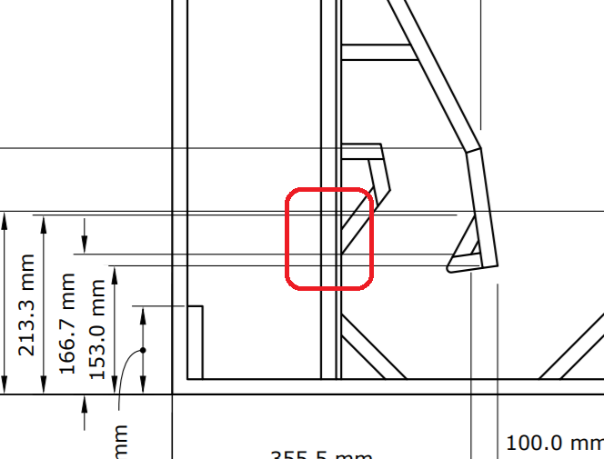 this look like quite a difficult angle to cut.. what is the angle? (CBA working it out) your CAD work looks great though. good stuff. |
||||
|
||||
|
snowflake
Old Croc
Joined: 29 December 2004 Location: Bristol Status: Offline Points: 3122 |
Post Options
Thanks(0)
Quote Reply
Posted: 27 May 2020 at 9:52am |
|||
changing to 45 degrees will make little difference acoustically. and you could make that part out of a piece of 2"*3" rather than three seperate pieces.
|
||||
|
||||
|
snowflake
Old Croc
Joined: 29 December 2004 Location: Bristol Status: Offline Points: 3122 |
Post Options
Thanks(0)
Quote Reply
Posted: 27 May 2020 at 9:54am |
|||
the offcut might be just big enought to make the triangle for the corner opposite too!
|
||||
|
||||
|
snowflake
Old Croc
Joined: 29 December 2004 Location: Bristol Status: Offline Points: 3122 |
Post Options
Thanks(0)
Quote Reply
Posted: 27 May 2020 at 10:01am |
|||
|
when I design something of this scale I usually round all the parts to the nearest 5mm and work from the mouth backwards adjusting all the parts to meet up. just makes it easier when you are cutting as most rulers and tools have their scales clearly marked in 5mm increments - will save a lot of squinting. round angles to 5degrees if possible. and most router depth guages have 3mm increments so make all your rebates either 3mm or 6mm.
Edited by snowflake - 27 May 2020 at 10:03am |
||||
|
||||
|
citizensc
Young Croc
Joined: 16 October 2015 Location: Perth,Australia Status: Offline Points: 532 |
Post Options
Thanks(0)
Quote Reply
Posted: 27 May 2020 at 10:36am |
|||
This does sound like a good idea, I think i'm just so paranoid about killing the 'magic' of the F2B that is described by people that have experienced it. Thanks for the comments so far, i'm taking it all onboard, I will focus on improving the quality of life for the builder in the next version. |
||||
|
||||
|
cravings
Old Croc
Joined: 30 January 2007 Location: Ireland Status: Offline Points: 7442 |
Post Options
Thanks(0)
Quote Reply
Posted: 27 May 2020 at 11:51pm |
|||
oh good call! |
||||
|
||||
|
Post Reply
|
Page <1 23456 9> |
| Tweet |
| Forum Jump | Forum Permissions You cannot post new topics in this forum You cannot reply to topics in this forum You cannot delete your posts in this forum You cannot edit your posts in this forum You cannot create polls in this forum You cannot vote in polls in this forum |


 Topic Options
 citizensc wrote: