 |
Tom Danley and Yorkville offer more... |
Post Reply 
|
Page 123 5> |
| Author | |
CoblosBrengose 
Registered User 
Joined: 09 December 2008 Location: Indonesia Status: Offline Points: 20 |
 Post Options Post Options
 Thanks(0) Thanks(0)
 Quote Quote  Reply Reply
 Topic: Tom Danley and Yorkville offer more... Topic: Tom Danley and Yorkville offer more...Posted: 18 March 2010 at 2:19am |
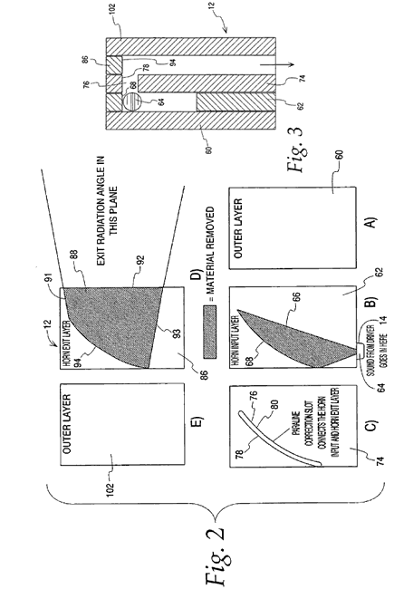
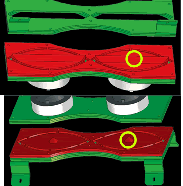
the danley paraline patent is now available for viewing through google. http://www.google.com/patents/about?id=nU3LAAAAEBAJ I haven't fully comprehend what's the correlation of Fig. 2 and Fig. 3 related to Fig 4/5/6.  by examining the patent, there are modification in VTC implemention, on the red plywood sheet pictured below in yellow circle: (1) adding cones in front of bms throat, and (2) trapezoids on exit slot.  I think it's DIY doable. Edited by CoblosBrengose - 18 March 2010 at 7:44am |
|
 |
|
jsg mashed 
Registered User 
Joined: 18 May 2007 Location: United Kingdom Status: Offline Points: 305 |
 Post Options Post Options
 Thanks(0) Thanks(0)
 Quote Quote  Reply Reply
 Posted: 14 March 2009 at 5:44pm Posted: 14 March 2009 at 5:44pm |
Looks right to me. You've shown the path area increasing gradually as per a horn and this is right I think. But in the top part, the area is expanding as the wave goes out radially, so instead of imposing an exponental profile, you'd want to impose the correction to get from conical to exponential.
The bottom part is more complex, but similar issues apply.
|
|
|
...because Good is Dumb.
|
|
 |
|
Tony Wilkes 
Old Croc 

Joined: 02 August 2004 Location: West Midlands Status: Offline Points: 4840 |
 Post Options Post Options
 Thanks(0) Thanks(0)
 Quote Quote  Reply Reply
 Posted: 10 March 2009 at 1:21pm Posted: 10 March 2009 at 1:21pm |
|
Mykey,
That's it exactly but it is oval in plan to give you the slot form output. It makes sure that all points on the slot have the same signal path length from the original source. Its just a more compact way of doing what BMS do with their L.A. HF driver. Tony Edited by Tony Wilkes - 10 March 2009 at 1:21pm |
|
 |
|
mykey 
Old Croc 
Joined: 18 August 2005 Location: UK/Indonesia Status: Offline Points: 9680 |
 Post Options Post Options
 Thanks(0) Thanks(0)
 Quote Quote  Reply Reply
 Posted: 10 March 2009 at 12:15pm Posted: 10 March 2009 at 12:15pm |
 |
|
audiodesignguide 
New Member 
Joined: 10 March 2009 Location: rome Status: Offline Points: 1 |
 Post Options Post Options
 Thanks(0) Thanks(0)
 Quote Quote  Reply Reply
 Posted: 10 March 2009 at 6:44am Posted: 10 March 2009 at 6:44am |
|
ArthurG, what do you suggest about a good 15" to use with CP380M ?
|
|
 |
|
haymere 
Young Croc 
Joined: 28 December 2007 Location: Liverpuddle Status: Offline Points: 585 |
 Post Options Post Options
 Thanks(0) Thanks(0)
 Quote Quote  Reply Reply
 Posted: 24 August 2008 at 8:45am Posted: 24 August 2008 at 8:45am |
|
Going back a bit I would just love to try some of danley/yorkvilles unity series
mark
|
|
 |
|
turbodeas 
Registered User 
Joined: 06 August 2005 Location: United Kingdom Status: Offline Points: 293 |
 Post Options Post Options
 Thanks(0) Thanks(0)
 Quote Quote  Reply Reply
 Posted: 24 August 2008 at 3:42am Posted: 24 August 2008 at 3:42am |
|
That did occur to me, but phase plugs are almost always centered on the
diaphragm, thus providing equal pressure across the vibrating surface.
I was concerned that the throats on cone transducers in line array systems are often off centre, surely creating an area of much higher pressure at the edge of the cone. Does this not mean a) that breakup can happen easier or b) that the radiated sound from one edge of the cone has to travel further to the throat than on the other? I might be completely wrong here, just trying to clear it up in my head but can't find much conclusive evidence either way! Cheers, Chris. |
|
 |
|
_djk_ 
Old Croc 
Joined: 23 November 2004 Location: United States Status: Offline Points: 6002 |
 Post Options Post Options
 Thanks(0) Thanks(0)
 Quote Quote  Reply Reply
 Posted: 23 August 2008 at 10:24pm Posted: 23 August 2008 at 10:24pm |
|
"I was just unsure of the effects covering half of the driver with wood/metal would have on the sound!"
You mean like a compression driver where 90% of the diaphragm area is covered by the phase plug?
|
|
|
djk
|
|
 |
|
turbodeas 
Registered User 
Joined: 06 August 2005 Location: United Kingdom Status: Offline Points: 293 |
 Post Options Post Options
 Thanks(0) Thanks(0)
 Quote Quote  Reply Reply
 Posted: 23 August 2008 at 6:49pm Posted: 23 August 2008 at 6:49pm |
|
Riiiiight.
I'm well aware of the effects 1/2 wavelength coupling has on sound, I was just unsure of the effects covering half of the driver with wood/metal would have on the sound! Thanks for clearing that up, it's appreciated :] Chris. |
|
 |
|
AshayinFLA 
New Member 
Joined: 22 August 2008 Location: South Florida Status: Offline Points: 3 |
 Post Options Post Options
 Thanks(0) Thanks(0)
 Quote Quote  Reply Reply
 Posted: 23 August 2008 at 3:14am Posted: 23 August 2008 at 3:14am |
|
I would think it would have an effect on the lf frequnecy response, but the main reason for that is actually to keep the "sources" of sound less than 1/2 a wavelength from each other. If the sound eminates from more than 1/2 a wavelength away (at the highest frequency the transducer is set to reproduce, since that is the smallest wavelength) then you can get phase cancellations and uneven frequency response across the listening area. That is why so many line arrays use small mid drivers (4-6") rather than larger (10-12") drivers which can reproduce the frequencies just as well. The larger drivers when set next to each other will be too far apart for the frequencies they produce, to keep even coverage at the edges of the coverage area (of course it is hard to hear the difference with music, especially while standing in one point, but if you play pink noise and walk around, the difference is very obvious very quickly, as you will hear the "shape" of the noise changing as you walk!). If you use larger drivers, you can make them "vent" out close together, so the sources of sound are close enough, you eliminate that problem!
|
|
 |
|
turbodeas 
Registered User 
Joined: 06 August 2005 Location: United Kingdom Status: Offline Points: 293 |
 Post Options Post Options
 Thanks(0) Thanks(0)
 Quote Quote  Reply Reply
 Posted: 23 August 2008 at 3:08am Posted: 23 August 2008 at 3:08am |
|
Ah cheers, that clears some stuff up for me.
So there's no problem with only one side of the mid driver being exposed/loaded? I was just always of the mind that the throat of a horn should come from the centre of the driver, in order to keep pressure across the cone equal - looking at the Danley boxes the mid throats are quite clearly at the edge of the cones..... Chris. |
|
 |
|
Centauri 
Old Croc 
Joined: 29 November 2004 Location: Newcastle Aus Status: Offline Points: 1792 |
 Post Options Post Options
 Thanks(0) Thanks(0)
 Quote Quote  Reply Reply
 Posted: 23 August 2008 at 1:05am Posted: 23 August 2008 at 1:05am |
That is usually the main reason - the higher the crossover frequency, the closer the two sources would need to be. There is also the problem of not having too many irregularities to the horn as far as the HF is concerned - a large hole in the side of the horn will degrade the HF significantly and cause large reflections. Note the vertical slots in the Vertecs. In some experiments I was doing, I brought the high mid throats out to vertical slots either side of the HF (similar to the Worx boxes) and found that covering these with a fine flat steel mesh improved the HF output. |
|
 |
|
Post Reply 
|
Page 123 5> |
| Tweet |
| Forum Jump | Forum Permissions  You cannot post new topics in this forum You cannot reply to topics in this forum You cannot delete your posts in this forum You cannot edit your posts in this forum You cannot create polls in this forum You cannot vote in polls in this forum |