
|
Linear Phase without FIR |
Post Reply 
|
Page <123 |
| Author | |
corell 
Young Croc 

Joined: 19 August 2013 Location: Berlin Status: Offline Points: 1161 |
 Post Options Post Options
") Thanks(0) Thanks(0)
 Quote Reply Quote Reply
 Posted: 14 September 2017 at 8:37am Posted: 14 September 2017 at 8:37am |
|
I was not assuming that the graph shown in post 1 was linear phase, as you said, it only appears to be because the scale is logarithmic. the point where gen0me and i disagree is if actual linear phase is "worse" than constant phase or not.
|
|
 |
|
|
gen0me
Young Croc
Joined: 20 February 2016 Location: UK Status: Offline Points: 999 |
Post Options
Thanks(0)
Quote Reply
Posted: 14 September 2017 at 11:23am |
|
You can figure out phase from gd. You cant figure out gd from phase due to -2kpi that changes across frequencies. You can only shoot it.
Here is whats really on my mind: For this top:   So according to: 
Leru choose best possible delay for phase measurement - top of bandwitch where gd is constant. Still interpreting it is impractical... Edited by gen0me - 14 September 2017 at 11:25am |
|
|
|
|
gen0me
Young Croc
Joined: 20 February 2016 Location: UK Status: Offline Points: 999 |
Post Options
Thanks(0)
Quote Reply
Posted: 14 September 2017 at 4:09pm |
|
Actually. Could you show us 3 seperate impulse responses and than combined one?
|
|
|
|
|
Jo bg
Young Croc
Joined: 08 March 2017 Status: Offline Points: 552 |
Post Options
Thanks(0)
Quote Reply
Posted: 14 September 2017 at 5:38pm |
|
Timo, i am so happy you proved me wrong
 thanks for your research and the helpful blog; i knew your videos with Linea flat phase crossovers but missed the posts you link here! thanks for your research and the helpful blog; i knew your videos with Linea flat phase crossovers but missed the posts you link here!can't wait to have some time to try this, i hope my xilica has got enough horse power to deploy all the all pass filters needed, at least for a 1 Khz crossover. In your experience, assuming the drivers tolerate a 2nd order crossover at that frequency, would this "linear phase through delay & all pass" be useful also at lower frequencies like 180 hz ? |
|
|
|
|
Timo Beckman
Registered User 
Joined: 09 August 2011 Location: Netherlands Status: Offline Points: 197 |
Post Options
Thanks(0)
Quote Reply
Posted: 17 September 2017 at 12:10am |
|
I did a experiment where i used a FIR on the highs from +/- 1K2 (i think but do not remember exactly)
and because of the latency on a Powersoft X8 when using FIR (+/- 4ms) i can use that latency to correct or better said alter the phase on the low driver (going down from 1K2 to about 63Hz if i remember correctly). The result looks kind of OK ;-). 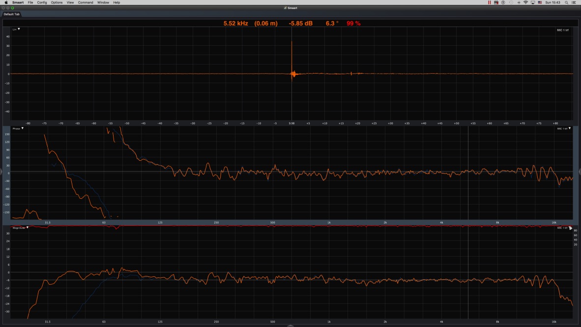 But this was just me "geeking" around to see what would happen on that mic position. I would not go as flat on a system as in the screen shot. (the ofax was a bit jumpy so it needed a "little" more work....;-)) The reason is pretty simple and has to do with subs......They will mess up things every now and then. I would try to go more to a single wrap on the low end around the x-vr and then go more gradually down to 0º. Maybe like this next screen shot from a Fulcrum RM25ac. (this is a point source system no sub in the screen shot and straight out of the box.) And here's a combination of 2 x RM25ac 2 x RM28ac 1 x FA28ac in a 5.1 surround set-up. https://timobeckmangeluid.files.wordpress.com/2017/04/5-1-all-on-small-room.png?w=2000 (there where 5 speakers playing during the screen capture). Here i had to use some AP2 filters to get the low end to work together. The RM25ac starts at 24Hz (high-pass filter somewhere around there and the RM28ac starts at 40Hz also a high-pass filter but at a different frequency and again the same thing on the FA28ac at 45Hz which was no problem with the RM28ac but was with the RM25ac). Also a flat frequency respons might not be what you want when you have to push a 99/105dBa. 2nd the phase flat/zero stuff from Lake and Linea is pretty cool but it doesn't mean you'll get a flat phase system because you still have to deal with the driver's respons. By the way i'm not trying to prove anything just showing some ways to go about measurements.
Edited by Timo Beckman - 17 September 2017 at 12:02pm |
|
|
The sound will be as good as the band play's
|
|
|
|
|
fatfreddiescat
Young Croc

Joined: 15 October 2010 Location: N.E.Wales Status: Offline Points: 1083 |
Post Options
Thanks(0)
Quote Reply
Posted: 17 September 2017 at 7:37am |
|
Hi Timo, thanks for posting, I have been reading your blog although had also missed the posts about ap filters and really appreciate the work you have put in.
|
|
|
|
|
Timo Beckman
Registered User
Joined: 09 August 2011 Location: Netherlands Status: Offline Points: 197 |
Post Options
Thanks(0)
Quote Reply
Posted: 17 September 2017 at 12:19pm |
|
If i take a look on the screen shot on the opening post:
From about 300Hz to 100Hz it's about 5ms of group/phase delay on that area. From about 1K to 300Hz it's about 1.42ms (1.43) of group/phase delay on that area. From about 5K5 to 1kHz it's about 0.22ms of group/phase delay on that area. You can calculate the group delay via this formula: (∆Phase/360º)/(∆Frequency) so for the first range 300Hz to 100Hz (360º/360º)/(300-100)=1/200=0.005 sec would mean 5ms. If you add 5ms to the synchronization delay within your analyzer the phase would go flat in the range 300Hz-100Hz somewhere in the middle. I do not see the specific frequency points so i took easy numbers ......(frequency scaling in decay setting is always a bit of a guess for me. I'ld rather set it to ⅓ oct scaling). (by the way you have to read the frequency points from right to left)
Edited by Timo Beckman - 17 September 2017 at 12:21pm |
|
|
The sound will be as good as the band play's
|
|
|
|
|
LeruSound
Registered User

Joined: 27 August 2015 Status: Offline Points: 171 |
Post Options
Thanks(0)
Quote Reply
Posted: 20 September 2017 at 10:48pm |
|
Here i posted some of the results..
https://forum.speakerplans.com/midtop-15-8-1-3-way_topic98579_post993292.html#993292 |
|
|
|
|
Post Reply
|
Page <123 |
| Tweet |
| Forum Jump | Forum Permissions You cannot post new topics in this forum You cannot reply to topics in this forum You cannot delete your posts in this forum You cannot edit your posts in this forum You cannot create polls in this forum You cannot vote in polls in this forum |


 Topic Options
 corell wrote: