2x15" front loaded horn F2B
Printed From: Speakerplans.com
Category: Plans
Forum Name: Other plans
Forum Description: Discussion / Questions about all the other plans
URL: https://forum.speakerplans.com/forum_posts.asp?TID=105216
Printed Date: 27 March 2026 at 5:14am
Software Version: Web Wiz Forums 12.08 - https://www.webwizforums.com
Topic: 2x15" front loaded horn F2B
Posted By: bob4
Subject: 2x15" front loaded horn F2B
Date Posted: 11 May 2020 at 8:15pm
|
no joke, no kidding....... I was asked by a gentleman to post these documents on his behalf (he prefers to stay anonymous). I had a private conversation with an elder forum member about this. He had no objection to me posting this. Take it for what it is...... I have no clue as to how accurate or correct these plans are. I am sure a discussion on the details will ensue....... So grab your popcorn, cork your bottles, drum roll.........  sorry for posting PDF files. I couldn't be arsed to convert all the documents, they are also incredibly compact in size.... I think this is the most crucial part of the plans, the details are in the rest of the documents. uploads/19/Martin_Audio_F2B_Grundriss.pdf" rel="nofollow - uploads/19/Martin_Audio_F2B_Grundriss.pdf uploads/19/Martin_Audio_F2B_Model_1.pdf" rel="nofollow - uploads/19/Martin_Audio_F2B_Model_1.pdf uploads/19/Martin_Audio_F2B_Model_2.pdf" rel="nofollow - uploads/19/Martin_Audio_F2B_Model_2.pdf uploads/19/Martin_Audio_F2B_Model_3.pdf" rel="nofollow - uploads/19/Martin_Audio_F2B_Model_3.pdf uploads/19/Martin_Audio_F2B_Model_4.pdf" rel="nofollow - uploads/19/Martin_Audio_F2B_Model_4.pdf uploads/19/Martin_Audio_F2B_Model_5.pdf" rel="nofollow - uploads/19/Martin_Audio_F2B_Model_5.pdf uploads/19/Martin_Audio_F2B_Model_6.pdf" rel="nofollow - uploads/19/Martin_Audio_F2B_Model_6.pdf uploads/19/Martin_Audio_F2B_Model_7.pdf" rel="nofollow - uploads/19/Martin_Audio_F2B_Model_7.pdf uploads/19/Martin_Audio_F2B_Model_9.pdf" rel="nofollow - uploads/19/Martin_Audio_F2B_Model_9.pdf uploads/19/Martin_Audio_F2B_Model_10.pdf" rel="nofollow - uploads/19/Martin_Audio_F2B_Model_10.pdf (I just realized that there seems to be a missing page, will add it when/if I get it)
|
Replies:
Posted By: snowflake
Date Posted: 11 May 2020 at 8:45pm
 |
Posted By: Danny A
Date Posted: 11 May 2020 at 8:58pm
|
Thanks Bob4 What would be a good modern driver for this design?
edit - I see that the L15-554K is the modern driver for this design
|
Posted By: bob4
Date Posted: 11 May 2020 at 9:20pm
|
 csg wrote:
Posted By: bob4
Date Posted: 11 May 2020 at 9:24pm
|
Posted By: bob4
Date Posted: 11 May 2020 at 9:25pm
..aaaaand, first one to calculate and post hornresp inputs gets a cookie 
|
Posted By: bob4
Date Posted: 11 May 2020 at 9:29pm
It says "alternative driver", no guarantee, take it with a tablespoon of salt. There are also warnings on several pages urging the prospective builder to evaluate driver clearances before attempting a build. You have been warned.
 |
Posted By: VECTORDJ
Date Posted: 11 May 2020 at 10:53pm
|
Your plans are A+ |
Posted By: madboffin
Date Posted: 11 May 2020 at 10:54pm
|
It is clear that those drawings have been made by studying an existing cabinet, and some of the detail is a bit off. For example - the parts drawn on page 5 (T5,6,7,8,12,13) should actually be two solid wood blocks, and the shape isn't quite right. If you make these with small pieces of plywood, you will probably end up with rattles after a period of use. It will take a while to check the dimensions for accuracy as they are all measured from different reference points to the original. If anyone tries to sim this - note that the void between T4, T10, and the horn flare is open to the rear of the baffle and adds to the back chamber volume. The cutaways in the baffle, giving access to that extra volume, were to provide clearance for the backing plates for the flying points that were fitted to the original cabinets. Obviously the flying metalwork is not needed for a ground stacked box. Would be interesting to see page 8 if you can get it, maybe it's a baffle drawing? |
Posted By: snowflake
Date Posted: 12 May 2020 at 12:17am
the L15-554K does fit easily. the other two RCF I mentioned don't.
|
Posted By: djeddie
Date Posted: 12 May 2020 at 8:56am
|
Well the outside dimensions match my 'extended' F2B's. And as I've said on this forum before, try them with the PD1550!
------------- Chas n Dave : it's like Drum and Bass but with beards. E=mc² ±3dB |
Posted By: concept-10
Date Posted: 12 May 2020 at 9:54am
It may well do externally but a PD1550 will not fit this plan, including the driver rebate you have about 155mm depth on this drawing, a PD1550 has a total depth of 160mm, I'm convinced this plan is not totally accurate to the original or the stretched ones. |
Posted By: citizensc
Date Posted: 12 May 2020 at 10:30am
| Is it really much of an issue to add 10 or 15mm depth to the rear chamber to accommodate a wider selection of drivers, as long as you keep the same rear chamber volume? Obviously the external dimensions wont batch a real F2B but if you have no intention of stacking them with existing F2Bs then who cares? |
Posted By: concept-10
Date Posted: 12 May 2020 at 11:19am
No it's not an issue, it's a good plan and while you are doing it you can get the rear chamber volume correct for the driver you are choosing, though I an not convinced it is 100% accurate to the original it is a very good starting point to make something very special.
|
Posted By: snowflake
Date Posted: 12 May 2020 at 12:07pm
Beyma 15LX60V2 |
Posted By: VECTORDJ
Date Posted: 12 May 2020 at 12:15pm
|
Hi bob4, Do You have any other plans?? |
Posted By: djeddie
Date Posted: 12 May 2020 at 3:57pm
There is another trick... and that's to route out a few mil in the access hatch.  ------------- Chas n Dave : it's like Drum and Bass but with beards. E=mc² ±3dB |
Posted By: levyte357-
Date Posted: 12 May 2020 at 5:06pm
 How realistic are the quoted response figures ? Has anyone tried extending this to 1220mm height, to fit across 2x modern subs? Looking at drivers, sure it would not be difficult find drivers that match the important TS parms, and adopt chambers accordingly.
------------- Global Depopulation - Alive and Killing. |
Posted By: levyte357-
Date Posted: 12 May 2020 at 5:12pm
Might be good for <150hz, but would it really excel above 200hz? ------------- Global Depopulation - Alive and Killing. |
Posted By: Jimmer
Date Posted: 12 May 2020 at 6:53pm
Flat upto 250 
------------- http://connect-av.co.uk" rel="nofollow - http://connect-av.co.uk |
Posted By: bob4
Date Posted: 12 May 2020 at 6:54pm
No, nothing of particular interest...... i just acted as a strawman in this case.....
|
Posted By: djeddie
Date Posted: 13 May 2020 at 8:56am
Can concur with that. ------------- Chas n Dave : it's like Drum and Bass but with beards. E=mc² ±3dB |
Posted By: citizensc
Date Posted: 14 May 2020 at 12:52pm
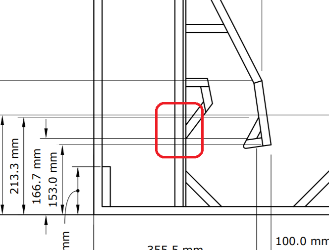
No need for the cookie, my lock-down baking game has been off the chain! My goal here isn't to draw up an exact F2B copy, there is some debate about how exact that plan is and I don't think an exact copy is that useful. A design that suites a wide range of drivers and can be built by a Disco Dave with a circular saw is more my kinda thing. I have drawn up a slightly modified version in sketchup with the goal of making the plan easier to build. I have replaced all the 15mm pannels with 18mm, this should have negligible impact as most of that extra wood has gone in to wasted cavity space. I also changed the baffle a little bit. The baffle now consists of a piece of 18mm ply with the driver cutout and rebate stuck to a 6mm piece of ply with the throat adaptor cut in to it. With these changes I wouldn't call this a difficult build, id rather build this than a double punisher (iv built 7 of those and they are a pain). I am not sure about the method I used to find the hornresp inputs. Below is an image of how I did it, black line is the path and dotted lines are the segments, where I measured the horn diameter. Id love some feedback on this, is there a best practice way of doing it?    2 drivers @ 4ohm  2 x F2B, 4 drivers @ 8 ohm  Once I get my sim parameters sorted, im happy to sim a number of different drivers. I will also go about increasing the depth of the rear chamber to accommodate more drivers. Here is a link to the sketchup drawing https://www.dropbox.com/s/1quejvp5zda1b7s/hornresp.skp?dl=0 |
Posted By: djeddie
Date Posted: 14 May 2020 at 3:38pm
|
One thing to bear in mind with the F2B is that it's a bifuricated horn... meaning it's two throats sharing one mouth, not two throats having "half the mouth" each (for want of a better phrase). Much like a HF horn that has two CD's on it... if you see what I mean. ------------- Chas n Dave : it's like Drum and Bass but with beards. E=mc² ±3dB |
Posted By: citizensc
Date Posted: 15 May 2020 at 12:09pm
Does it really make much difference? Would there be a meaningful change in performance if you extended panel Ty the full depth of the cab? |
Posted By: levyte357-
Date Posted: 15 May 2020 at 12:19pm
|
Any one interested in making this cab as 2x singles? ------------- Global Depopulation - Alive and Killing. |
Posted By: citizensc
Date Posted: 15 May 2020 at 12:32pm
Honestly, I was already thinking about doing that, was just a little worried people would get their nickers in a twist over it. |
Posted By: Robbo
Date Posted: 15 May 2020 at 1:30pm
| No point in building singles when the original is very compact in the first place. |
Posted By: levyte357-
Date Posted: 15 May 2020 at 1:40pm
Actually this is one of the reasons I never utilized this cab. A double for me needs to be at least 1200H, so it can lay across the top of 2x subs. Which is why THL828 is great size, even though it can't do what this cab will. ------------- Global Depopulation - Alive and Killing. |
Posted By: citizensc
Date Posted: 16 May 2020 at 5:15am
An F2B weighs 107kg according to the spec sheet, according to the spec sheet of the PA100-375 Bass it has a shipping weight of 17 kg, so the driver is ~15kg. If a modern 15 inch neo driver weighs <5kg, you can get the weight below 45kg in theory. If given the option of a 107kg original or two 45kg singles loaded with neos, I know which id rather move. Another thing of note is the impedance curve of my sim isn't too different to the martin spec, suggesting I may not be far off the mark. 
|
Posted By: citizensc
Date Posted: 16 May 2020 at 11:39am
|
lil update I did some playing and I think I got some better hornresp inputs (See pics for method and new inputs). I also simmed a bunch of different drivers, a lot of the 3 inch vc neos work well like the 15nd930 and 15NDL76 but they are very deep, they are all close to 180mm, the original driver is 145mm for reference. The RCF 4 inch vc neos are close and have a depth of 160mm. Both the MB15N405 and MB15N401 sim well but the 401 has a very high BL and low QTS, I dont know for sure but I suspect it will sound a bit too hard and a bit too dry. The 405 sims better than the original driver (see pics) and has huge power handling so it should be hard to kill in theory. I added a 10mm rebate to the drawing, to make space for the driver. I did a lot of playing with different rear chamber volumes in hornresp, regardless of driver it seems happiest when left at the original volume of ~46L after subtracting volume of the driver. tldr: my drawing is exactly the same as the original in horn dimensions and very close in rear chamber volume, some slight changes have been made to make it easier to build and remove the need for 15mm ply, the MB15n405 may be the best driver for it. One question, the current drawing leaves about 3mm of clearance behind the driver, is there going to affect performance?  Current sketchup drawing showing 10mm clearance for driver and new method of finding hornresp inputs.  New hornresp inputs   1 x F2B at 4 ohm Black=PA100-375 Bass, Grey = MB15N405  2 x F2B at 8 ohm Black=PA100-375 Bass, Grey = MB15N405 Link to sketchup drawing https://www.dropbox.com/s/wmyzdnscotz79p0/hornrespv2.skp?dl=0 |
Posted By: APC321
Date Posted: 16 May 2020 at 1:33pm
|
3mm clearance behind the driver does not seem enough to me, bearing in mind the venting arrangements used to cool most voice coils. I have previously taken a bass driver (with a circular central cooling vent) and fed it with a low frequency sine wave tone to get significant cone movement. This was done to check for a rubbing voice coil. When the driver was in free space you could tell that the cooling system was working properly and "pumping" a lot of air. But when the driver was moved closer to the top of a work bench there was a change. With the cooling vent less than maybe 15mm above a bench you could hear a change in the sound similar (but not as great as)to blocking the vent with your hand. So I would think that the cooling system of the driver was being affected, and the driver was not operating under ideal conditions. |
Posted By: DMorison
Date Posted: 16 May 2020 at 1:41pm
JBL always recommended 76mm (three inches for the metrically challenged) minimum gap behind their 2226 for adequate cooling, FWIW. I know modern drivers often have extra cooling between the chassis and suspension, so that will help, but my gut instinct is that only 3mm is still way too small a gap.
|
Posted By: madboffin
Date Posted: 16 May 2020 at 4:40pm
|
The F2B was constructed with 18mm ply, not 15mm. But the baffle used two pieces of thinner ply glued together to make up an overall thickness of 25mm or so. You will need to provide clearance for the rear vent on the drive unit. Even the original was barely adequate, and could have done with more. |
Posted By: citizensc
Date Posted: 17 May 2020 at 11:59am
Interesting that the drawing from page 1 has parts that are made of 15mm. Look at the PDF for model 5. I have constructed the baffle in the same way on my drawing, an 18mm piece sandwiched with a 6mm piece. 6mm birch isn't that expensive and you don't need much, I don't think its too much of a stretch for anyone building this to buy some. Thanks for all the advice on driver clearance, I've bitten the bullet and stretched out the rear chamber by 12mm, adding 24mm of total width to the cab making it 1090mm(its the end of the world I know). This leaves 15mm of clearance including the 10mm routed out behind the driver. Considering the original only left 8mm clearance I think it should be fine. I have sealed off the chamber connected to the mouth of the horn in order to keep the rear chamber volume almost the same (less than 1L difference). Anyway I think the current drawing is close to usable, I don't foresee any significant issues with building it and if the sim is anything to go by, it should sound good.  Sketchup drawing https://www.dropbox.com/s/pjupfqyumvzac77/expanded%20rear%20chamber.skp?dl=0 |
Posted By: APC321
Date Posted: 17 May 2020 at 6:28pm
|
When I said: "With the cooling vent less than maybe 15mm above a bench you could hear a change in the sound similar (but not as great as)to blocking the vent with your hand." I probably would not use this dimension of 15mm as a basis to work out dimensions when building a box. Far too un-scientific! My disclaimer! Does seem too close to me if you want to avoid all unwanted effects. Especially as the back of the f2b is perpendicular (at 90 degrees) to the vent. ie. parallel to the face of the magnet. I would have thought that you would get some sort of "back pressure" effect that could affect the response of the driver in the box, as well as it's cooling. |
Posted By: madboffin
Date Posted: 17 May 2020 at 11:10pm
Yes, but that's not a perfectly accurate drawing, although it's quite close. One thing to be aware of is that all the internal woodwork should be rebated into the two large side panels, and the baffle also rebated into the rear panel. I'd recommend rounding off that sharp corner in the first section of the folded horn, otherwise there's a risk of chuffing noises. The original box used a shaped piece of wood there - see my note further up the thread. If you search the forum there is quite a lot of information on these boxes that might be helpful, although it will take a bit of finding. I used to work for Martin Audio and built some of the original boxes. By the way - did you know that the late lamented Dave Martin grew up as a farmer's boy, somewhere near Bunbury? |
Posted By: citizensc
Date Posted: 18 May 2020 at 11:56am
The original driver is rear vented and only had 8mm clearance - see pic below I didn't give it 15mm clearance to match your test, I just felt it was a good amount, almost double that of the original F2B which had no issues. I suspect it will be fine but id love to hear some more opinions, will it cause issues? is it fine?
I was just expecting people to do this, I've done it on all my builds. I would imagine if you didn't the cab would rattle and eventually fall apart.
Thanks for the idea, I have updated the drawing with a 1cm radius bevel, see the image below. As far as potential rattling, based on my past experience I don't think it will. I have 6 double punishers and 4 xtros that have ~100 gigs under their belt with 0 rattles, cabs are still solid, despite being made of 15mm ply. The F2B being made of 18mm has to count for something, also, I have drawn joins so the panels can easily be screwed and glued together. The cab should be rock solid, especially around those cavities.
I have done a bit of reading, a lot of interesting posts, interesting how accurate peoples descriptions are despite there being no publicly available plan, even in posts from a decade ago. In my mind, I saw Martin Audio as the most English thing since Wallace and Gromit, had no idea the man him self was from Western Australia! although I can imagine most of the people there were English. Thanks very much for your help guys, its very much appreciated! Up to date drawing: https://www.dropbox.com/s/pjupfqyumvzac77/expanded%20rear%20chamber.skp?dl=0   |
Posted By: snowflake
Date Posted: 20 May 2020 at 12:45am
|
it looks to me like the RCF spec sheet for the MB15N405 has a mistake on it - the Mmd of 79.4 looks unlikely because it doesn't work with the other physical paramters to give the correct t/s parameters. maybe the correct Mmd is the figure they have given for Mms - 98g. Still seems like the best driver for this box by a good stretch though. |
Posted By: citizensc
Date Posted: 21 May 2020 at 11:38am
I used the dialogue box below to enter the driver paramaters, It calculates Mmd from that. The Mmd I used in the sim was 96.38.  A member messaged me about the PD.1550, it is only 156mm deep, it should fit fine with my modification to the rear chamber. You may need to increase the radius of the clearance behind the driver to accommodate the larger magnet. In sims, its a tiny bit less sensitive than MB15N405 but it looks fine to me. PD.1550 is quite heavy. If I were buying new drivers, id go for the MB15N405 but if you have some pd.1550 laying around, they should work fine. Grey=MB15N405, Black = PD.1550, 2 F2B @ 8 ohm, 2.83v. 
|
Posted By: concept-10
Date Posted: 21 May 2020 at 8:40pm
Very nice 
|
Posted By: citizensc
Date Posted: 27 May 2020 at 7:25am
|
Due to sketchup not being everyone's favourite software, I have made a 2d drawing of the cab. I'm not an engineer and am still open to learning, any feedback on the cab or the documentation is welcome. I have attached a PDF as well as the .png image, I strongly recommend to anyone building this, use the PDF, its much clearer. Let me know if I have missed any important measurements. PDF: https://www.dropbox.com/s/o8lpfykep02a7qo/v0.1b.pdf?dl=0 Sketchup: https://www.dropbox.com/s/bzn9hki99oc8si8/v0.1b.skp?dl=0  |
Posted By: cravings
Date Posted: 27 May 2020 at 8:28am
 this look like quite a difficult angle to cut.. what is the angle? (CBA working it out) your CAD work looks great though. good stuff. |
Posted By: snowflake
Date Posted: 27 May 2020 at 9:52am
changing to 45 degrees will make little difference acoustically. and you could make that part out of a piece of 2"*3" rather than three seperate pieces.
|
Posted By: snowflake
Date Posted: 27 May 2020 at 9:54am
the offcut might be just big enought to make the triangle for the corner opposite too!
|
Posted By: snowflake
Date Posted: 27 May 2020 at 10:01am
|
when I design something of this scale I usually round all the parts to the nearest 5mm and work from the mouth backwards adjusting all the parts to meet up. just makes it easier when you are cutting as most rulers and tools have their scales clearly marked in 5mm increments - will save a lot of squinting. round angles to 5degrees if possible. and most router depth guages have 3mm increments so make all your rebates either 3mm or 6mm. |
Posted By: citizensc
Date Posted: 27 May 2020 at 10:36am
This does sound like a good idea, I think i'm just so paranoid about killing the 'magic' of the F2B that is described by people that have experienced it. Thanks for the comments so far, i'm taking it all onboard, I will focus on improving the quality of life for the builder in the next version. |
Posted By: cravings
Date Posted: 27 May 2020 at 11:51pm
oh good call! |
Posted By: snowflake
Date Posted: 28 May 2020 at 1:45pm
|
if you make all the parts in red out of solid timber that baffle is going to incredibly well braced. you could make that 6mm baffle piece even thinner to wrangle 2mm or 3mm extra. I assume the original design had flares expaning the letter box in the vertical dimension in that first few centimetres of the throat. maybe make the 18mm baffle piece smaller and removable with the driver. that way if you ever want to use a different driver with different sized cutout, bolt pattern, or want to increase excursion clearance above 18mm, you can just make a new baffle. fix it into the solid timber points with eight large threaded inserts and should be solid. you need to be careful rebateding that much out of the panel behind the driver. going from 18mm to 8mm reduces the stiffness by a factor of about 11. it's not a massive area but it could be enough to reduce the Q of the rear enclousure and affect the system efficiency. How about using an aluminium plate for the access panel - aluminium is about ten times stiffer than plywood. its an extreme, but for an example system - if Qmc falls from 20 to 5, system efficiency goes down from 46% to 35%, which reduces thermally limited max output by ~2dB  |
Posted By: ceharden
Date Posted: 28 May 2020 at 9:30pm
|
Not to mention that having the panel that thin makes it liable to external damage.
I would normally want to stiffen a panel in the rear chamber, not weaken it. The pressures are quite significant. 8mm aluminium would be good and act as a heat exchanger.
|
Posted By: snowflake
Date Posted: 28 May 2020 at 10:05pm
also you need to place some recessed bar handles - only place they can really go is on the rear chamber. fit them with gaskets and mounting plates to get them totally airtight and stiff. and even more heatsinks!
|
Posted By: citizensc
Date Posted: 29 May 2020 at 6:36am
|
One of my main goals for this is to keep it easy to build. Part of that is keeping the bill of materials and list of skills required to build it short. Having said that these are some good ideas. A member is building two of these as we speak, will suggest he start conservative with removing material behind the driver. In the next version of the plan (to come after feedback from the builder) I will point out that there are options to improve on a simple plywood design eg. aluminium access hatch and using solid timber to make all the parts in red. Thanks for the feedback. |
Posted By: snowflake
Date Posted: 29 May 2020 at 9:26pm
|
I just realised something about this F2B horn. leaving the first few centimetres of 'rubber throat' aside, even if you calculate a hyerbolic horn with M=0 it still doesn't expand quite as slowly at the throat and as quickly near the mouth as this horn. I was wondering why none of my designs based on Leach's reactance annulling came anywhere close to the F2B. So what is the theory behind this? |
Posted By: Digbethdave
Date Posted: 30 May 2020 at 11:14pm
|
You got to remember this was all designed as a system. Part flown. Part ground stack. |
Posted By: djeddie
Date Posted: 31 May 2020 at 1:00pm
And? ------------- Chas n Dave : it's like Drum and Bass but with beards. E=mc² ±3dB |
Posted By: tilla
Date Posted: 07 July 2020 at 9:09pm
|
Hey guys, great thread! Thanks for sharing all the knowledge and info here, enjoyed reading all. Just recently, I bought 4 of the F2Bs unloaded and now I am debating what to load them with. I d like to ask you guys to help me out to have a good idea of what would be the best ( most cost effective as well of course) option. I have two pairs of PD156s which I could use in two of them , they will just about to fit with a little modification to the mounting area in the box. What do you guys think how will this sound ? I also have a pair of RCF L15P-200/a which i m thinking to fit in the third one and maybe get a pair of these to the forth F2b. I understand that the above may not be ideal and of course all boxes with the same matching drivers are the real deal. This may be on the radar next year but for now i need to work with what I have. Whats do you guys think ? |
Posted By: Digbethdave
Date Posted: 07 July 2020 at 10:15pm
Also a good reason for 1/4 pack. I don't personally think ythe F2B needs redesigning, to the extent it now becomes something different. It's a good box, it is what it is. And I applaud people like jimmer who use it for what it is.
|
Posted By: madboffin
Date Posted: 08 July 2020 at 9:36am
|
To be strictly accurate, it was specifically designed to be as versatile as possible, and equally usable stacked or flown. Anyway I have found another picture, mixed stacked and flown, using the retrofit Technique fly bar system for the mids and tops: http://www.spamabyss.net/pictures/F2NNSL.jpg" rel="nofollow - http://www.spamabyss.net/pictures/F2NNSL.jpg |
Posted By: snowflake
Date Posted: 08 July 2020 at 1:11pm
those drivers won't be terrible but you would do a lot better getting eight matching: http://www.loudspeakerdatabase.com/RCF/MB15N405" rel="nofollow - http://www.loudspeakerdatabase.com/RCF/MB15N405 or http://www.loudspeakerdatabase.com/Beyma/15P80Nd" rel="nofollow - http://www.loudspeakerdatabase.com/Beyma/15P80Nd have a think about bolt patterns and whether it will be easy to upgrade to other drivers in future. |
Posted By: concept-10
Date Posted: 08 July 2020 at 1:55pm
those drivers won't be terrible but you would do a lot better getting eight matching: http://www.loudspeakerdatabase.com/RCF/MB15N405" rel="nofollow - http://www.loudspeakerdatabase.com/RCF/MB15N405 or http://www.loudspeakerdatabase.com/Beyma/15P80Nd" rel="nofollow - http://www.loudspeakerdatabase.com/Beyma/15P80Nd have a think about bolt patterns and whether it will be easy to upgrade to other drivers in future. |
Posted By: citizensc
Date Posted: 28 August 2020 at 8:51am
|
I received a PM regarding how well different drivers work in this cab, I have simmed a bunch of drivers in AKABAK 3 and hornresp to try help answer this question. Please don't treat these results as absolute but more of a guide of how different drivers MIGHT work. Nothing beats actually building a cab and trying a driver out, your ears will tell you if it sounds good. All sims are of a single f2b, (2 drivers). The hornresp sims are 2 x 8ohm drivers in parallel @ 2v (1watt total), the AKABAK sims are not referenced to any voltage. All sims use the ATC PA100-375 BASS as a reference, the ATC is grey in the hornresp sims, blue in the AKABAK sims. Kappa 15LF Hornresp  Kappa 15LF AKABAK  KAPPA PRO-15LF-2  KAPPA PRO-15LF-2  pd.1550  pd.1550  MB15N405  MB15N405  MB15N401  MB15N401  Seems hornresp sims FLHs quite well, the sims don't look that far off AKABAK. More sims to come, ask here or PM me if want a driver simmed. |
Posted By: Robbo
Date Posted: 28 August 2020 at 10:55am
|
Don't forget that the greatest limiting factor for drivers that will work in an F2B is the fact that they will physically fit inside the cabinet and allow the trap door to fit correctly making an allowance gap between the central magnet cooling hole and the inside surface of the the trap door. MOST POPULAR 15" BASS DRIVERS WILL NOT PHYSICALLY FIT IN A STANDARD F2B hence why only low profile chassis like the ATCs and certain RCF models are the only drivers that have been used in the past. |
Posted By: citizensc
Date Posted: 28 August 2020 at 12:57pm
This is a very good point and something I forgot to mention, measure twice, buy once! |
Posted By: citizensc
Date Posted: 29 August 2020 at 8:24am
|
Some more sims... PA100-375 Bass is now in blue in AKABAK sims which should help colour blind people out. L15P200 AK-II  L15P200 AK-II
 PD.156  PD.156  15P80Nd  15P80Nd  15P80Fe  15P80Fe  The 15P80Fe and Nd may actually survive in the horn, the MMS of both of them is actually 4 grams more than the PA100-375 Bass. I guess someone will have to try it to be sure. |
Posted By: Tonskulus
Date Posted: 29 August 2020 at 11:19am
|
L15P200 series has quite thin/flimsy paper cone, but however these has been used succesfully in some horns? I using P200A's in reflex, and they are good drivers there. Cannot stop thinking about the added distortion caused by cone flexing under high pressure.. at least symmetrical cone loading would be a good idea with these. |
Posted By: citizensc
Date Posted: 29 August 2020 at 12:54pm
It wouldn't be my pick but someone on the previous page asked about it, I don't think you need to spend much money to find a better driver for an F2B.
|
Posted By: citizensc
Date Posted: 01 September 2020 at 5:49am
|
I hate to admit it but I have had a bit of an egg on face moment. Long story short the previously posted AKABAK sims had a major issue, there was a glitch when I meshed the internal panels, resulting in a bunch of holes. For those that are not familiar with AKABAK 3, imaging building a cab with half the internal panels missing and then measuring it... I have updated my original posts with new sims and change the text to make sense in context with those sims. The new sims look really good, actually pretty close to hornresp! Anyway, I am very sorry about this, the new sims don't change the story, we have the same winners and losers but they are much more accurate. |
Posted By: snowflake
Date Posted: 01 September 2020 at 1:21pm
| does the peak at 350Hz disappear when you model three or four speakers stacked? |
Posted By: MarjanM
Date Posted: 01 September 2020 at 1:48pm
It seems like everyone have ignored Lev here. I was wondering the same thing. Substantially flat to 40Hz? HOW? ------------- Marjan Milosevic MM-Acoustics www.mm-acoustics.com https://www.facebook.com/pages/MM-Acoustics/608901282527713 |
Posted By: Tonskulus
Date Posted: 01 September 2020 at 2:01pm
|
Impedance is not flat, so real input power vs. frequency is not constant either using constant voltage source as is the case when measuring typical response curves. So it is not uncommon to see much different response curves when using constant power instead of constant voltage, maybe that is the case here as it says "power response". Who knows, I would like to see the impedance curve. Using constant power, you will see the efficiency curve. |
Posted By: snowflake
Date Posted: 01 September 2020 at 2:04pm
| I guess they have a generous interpretation of 'substantially'. |
Posted By: citizensc
Date Posted: 02 September 2020 at 6:16am
It does not, but I think it is likely an artifact of the simulation, one of the options for the simulation is 'mesh density', lower values increase accuracy at higher frequencies. Mesh density was low for this as simming multiple large cabs with high mesh density takes a loonnnggg time, hours... Here is a plot for 1 cab in red, 2 in blue. The one cab sim is 2v @ 4 ohm, the two cab sim is 1.41v @ 2 ohm, measured from 1m. 
You don't have to back up your claims if you use poorly defined terms like 'Substantially flat'. My punishers are substantially flat to 10hz ... what ever that means. Having said that, the -10db point is below 50hz for 2 stacked cabs. I can see how people find these to be usable as a one way bass solution.
Maybe its because i'm not an electrical engineer but I do not find AKABAKs labelling intuitive. There are two types of source in AKABAK 3; Potential Source and Flow Source. I have been using Potential because to my understanding, voltage is a measurement of difference in potential. I have tried flow, and it gives wacky results, I suspect this is constant power rather than constant voltage. Here are the impedance curves Red is 2 cabs @2 ohm, Blue is 1 cab @ 4 ohms.  |
Posted By: citizensc
Date Posted: 03 September 2020 at 11:37am
|
I received some actual real world feedback about different drivers in this cab. Thank you very much to the user that sent this to me and gave permission to relay the information to this thread. Here are a couple of quote from him: First he tried the pd.1550, this was back in may 'it's all true, the FB2 is a bloody monster  , built an MDF prototype with very tired 1550s and only a CA9 and it is stunning' , built an MDF prototype with very tired 1550s and only a CA9 and it is stunning'A couple of says ago he tried the 15P80Nd and Kappa 15LF 'ran the cab with the neo Beymas on Sunday, bloody hell it makes a noise, running of half a CA9 the impact was very strong, the CA9 is giving it nothing like the power it needs but it was very impressive, the impact and tonality is better than the 1550' 'The Kappas are a no go, sound terrible, going to run the Beymas very hard at the weekend and see how they last,' |
Posted By: snowflake
Date Posted: 03 September 2020 at 4:30pm
|
bit of ripple but get better in a stack: http://www.loudspeakerdatabase.com/Radian/2216Neo%20" rel="nofollow - http://www.loudspeakerdatabase.com/Radian/2216Neo
|
Posted By: BJtheDJ
Date Posted: 03 September 2020 at 9:40pm
You left a space on the end of the URL when you cut n pasted, which makes the URL look like this: http://www.loudspeakerdatabase.com/Radian/2216Neo%20 http://www.loudspeakerdatabase.com/Radian/2216Neo" rel="nofollow - http://www.loudspeakerdatabase.com/Radian/2216Neo Above will work
------------- I started out in this business with nothing. I still have most of it left. |
Posted By: bass*en*mass
Date Posted: 03 September 2020 at 10:44pm
|
at 750usd each the radian option doesnt look tempting tbh., compard to 15ds115 or 15nmb1000?
|
Posted By: jazomir
Date Posted: 08 September 2020 at 7:27pm
|
Interested as to whether anyone is able, or has been able, to test a group of say, 4 F2Bs with any of the new drivers. I would think that the lf extension of 4 cabs arrayed correctly could at least match a similar number of scoops. The punch of the originals would seem to have been impressive, to say the least, so adding new drivers and several thousand 'extra' watts of input would seem to promise extreme results.
------------- For sidefills, can we have two enormous things of a type that might be venerated as Gods by the inhabitants of Easter Island, capable of reaching volumes that would make Beelzebub soil his pants. |
Posted By: madboffin
Date Posted: 08 September 2020 at 8:38pm
|
Running modern power levels and very high-powered drivers would probably require some extra cooling - certainly more space behind the speaker vent, as discussed previously. In the original system the drivers could get quite warm during a day of loud rock bands at a festival and there would definitely be some power compression. I can remember unstacking large festival systems at the end of a string of heavy metal performances and finding the covers on the speaker chambers warm to the touch. Maybe make the baffle with a thick sheet of aluminium between the driver frame and the wooden board, or invent some clever form of driver cooling using a heatsink with air or liquid heat transfer? Or just accept that the world has moved on and design a new box more suited to modern requirements, although I suspect Tom Danley has covered that need already! It might be best to keep these vintage boxes more or less as they were designed, they work very well for what they are. |
Posted By: DMorison
Date Posted: 09 September 2020 at 1:33pm
|
Madboffin, you're going to have to change your handle to SensibleBoffin if you keep this up
|
Posted By: citizensc
Date Posted: 12 September 2020 at 10:33am
|
With the aluminium panel, I think cooling should improve a lot, especially as it should be exposed to fresh air in most stacking configurations. If you are really committed to cooling the driver you could connect the driver to the panel with a piece of metal, turning the panel in to heat sink for the driver. I think as far as designing a new box goes, there are lots of diy kick bins around, I think people just like the way this one sounds. Apart from clearance behind the driver, I am not sure what else you can do to improve cooling, warm rear chambers are common in FLHs. Worse case, you have to reduce power by 1-2dB to prevent overheating but lets be honest, if you are pushing it that hard, maybe you don't have enough rig for the gig. When I get time I will sim the 15nmb1000 and the Radian. I am not going to sim the 15DS115 as i know it will sound awful in this cab, even if you somehow make it fit. Even the sales people from B&C say it doesn't sound good over 150hz, its really intended as a sub driver. |
Posted By: bob4
Date Posted: 12 September 2020 at 9:53pm
Check out Wayne Parham and 12pi audio. They had come up with a heat transfer aid for labhorns, that involved a piece of thick aluminium pipe machined precisely to fit the polevent of the transducer (aided by thermal paste lubing  ) and then attached/bolted to the aluminium service hatch. ) and then attached/bolted to the aluminium service hatch. http://audioroundtable.com/PiSpeakers/messages/17535.html" rel="nofollow - http://audioroundtable.com/PiSpeakers/messages/17535.html http://www.pispeakers.com/Hornsub.html" rel="nofollow - http://www.pispeakers.com/Hornsub.html
|
Posted By: TribeGut
Date Posted: 05 November 2020 at 7:25pm
|
In the Hornresp simulation on page3 S4 is 2750. If taken into account that the share one horn, S4 must be around 5000. With S4=5000 you get a way better response nearly flat. But also this would mean splitting the horn in two parts is not possible without making the cab wider?
|
Posted By: Contour
Date Posted: 05 November 2020 at 7:54pm
| Not correct, there are 2 drivers so mouth area ‘seen’ by one unit is half of the total cabinet front area. |
Posted By: TribeGut
Date Posted: 06 November 2020 at 11:44am
Is there any theory behind it that would back this up, I think they share one mouth from S3-S4 so S4 musst be the total front area or at least more than half. Also if I set S4=5000 i get way better results in the simulation with one or two drivers..
|
Posted By: Contour
Date Posted: 06 November 2020 at 1:24pm
| So if I would make design where 10 driver share one mouth I could get same response as 10 boxes of ten times the total size? That would be nice, however it does not work like that, no free lunch. |
Posted By: TribeGut
Date Posted: 06 November 2020 at 4:26pm
I doubt that  but also think that just simulate it as a halve horn is not perfekt. but also think that just simulate it as a halve horn is not perfekt.Would totally appreciate it if you are right because that would mean splitting them in halve and build singles would work so no reason to build doubles. Never the less from experience I am skeptical with S4=2750  with S4=5000:  Obviously it wouldn't make sense to build Single cabs with a mouth area this big. But making them a bit wider to fit existing cabs would also improve the output, the bigger S4 the better results i get in the simulation. Please correct me if I'm wrong, still learning  |
Posted By: snowflake
Date Posted: 06 November 2020 at 4:40pm
|
two half cabs is exactly the same as one full cab. if you change the shape of the half cabs you have changed the system so it's going to have different response. the F2B was designed to be use in multiples. |
Posted By: djeddie
Date Posted: 06 November 2020 at 6:39pm
|
Google the term "bifuricated horn". It will probably give one or two results from this forum (and posts from myself!) but will also give an explanation of the theory behind it.
------------- Chas n Dave : it's like Drum and Bass but with beards. E=mc² ±3dB |
Posted By: jazomir
Date Posted: 05 January 2021 at 7:27pm
Isn't that what Danley does with the Jericho cabs and, for h.f., the paraline lens? ------------- For sidefills, can we have two enormous things of a type that might be venerated as Gods by the inhabitants of Easter Island, capable of reaching volumes that would make Beelzebub soil his pants. |
Posted By: Sonic the hedge
Date Posted: 14 October 2021 at 2:53am
If I'm understanding things correctly (and I'm by no means any sort of expert!) I think you are probably right to be paranoid. Slot loading, presents asymmetric cone loading, which causes the diaphragm to flex significantly. I know this for certain, because powerful strobe lighting was a thing, in the early 90s UK rave scene! Also, I used to periodically rotate the drivers in my 215s through 90 degrees, to stop the diaphragms getting bent too far out of shape. Interestingly, the drivers were mounted with L clamps, so perhaps this practice was foreseen/intended by MA? My theory (and please do tell if I'm talking shite!) is thus - the flexing of the cone diaphragm is intentional and key to the performance of these cabinets. It has two effects, which fall completely outside the scope, of established, conventional, speaker design principals: 1) The flexing somehow divides the 'effective' circumference of the driver, such that it behaves like a smaller driver, enhancing HF extension. Of course the narrow throat, permits a lower tuning, in a smaller cabinet also. Hence the remarkable, seemingly impossible, bandwidth and efficiency of F2B and similar slot loaded cabinets. 2) The flexing, along a single axis, forces cone breakup into a state, where 2nd/even order harmonics dominate, such that the massive amounts of HD, thus produced, enhances both output and tone, in a way that sounds pleasant. Unlike most other designs, well tuned slot-loaded FLH actually sound better when spanked hard! With this in mind, it can be seen, that the tuning of the flare is absolutely critical. Because to avoid growling or similar, the HD produced by diaphragm flexing must be kept within the pass-band. And the energy from out-of-band HD, acoustically filtered, has to go somewhere... Faithful reproduction it isn't...but if it sounds great, who cares! Incidentally, having read some of your previous posts, about what you are aiming to do with your rig, I think you will find F2B very interesting. Its worth me pointing out, that F2 was pretty much the default rig, in the early 90's UK breakbeat hardcore/jungle mega-rave scene. That was IMO, to to this day, the largest single-genre dance scene, that ever existed, with single-arena events of 10K-50K attendance not uncommon, as well as a huge number of smaller events, every weekend. From the mid 90s on, the scene split and fragmented musically, resulting in the multi-arena/festival type formats that are more common today, in the UK at least. Anyways, eventually Jungle morphed into what we now call Drum and Bass, so I think you can probably see, how that's all relevant, to what you are trying to do
|
Posted By: snowflake
Date Posted: 14 October 2021 at 8:32am
not sure about this idea. I don't think that drivers with particularly flexible cones have been used in designs like these. so there has been no intention to encourage greater cone breakup I'm not sure breakup modes do give a musically nice amount of second harmonic distortion. If anything slot loading puts a more even load on a driver. This can allow higher maximum powers through drivers as it stops the cone from ripping at points of exceptional pressure and stops the voice coil rocking and touching the sides of the gap. Slot loading reduces path length differences in the throat which lead to a cancellation if one side of the driver is further from the horn mouth. This produces a cancellation at a wavelength twice the diameter of the driver which is 450Hz for a 15" driver.
If you did want to produce loads of second harmonic then just add some distortion with an effect unit. |
Posted By: toastyghost
Date Posted: 14 October 2021 at 8:53am
| All horns produce many orders of magnitude more second-order harmonic distortion than they do any other type. |
Posted By: snowflake
Date Posted: 14 October 2021 at 11:42am
a notable thing about the F2B is that its expansion approximates to hyperbolic with T=0 which maximises such throat distortion. there's a useful diagram in Olson showing distortion levels for power/area of an exponential horn but I have never seen the equivalent for a hyperbolic horn. Hornresp can calculate distortion for single segment horns - this suggests changing T from 1 to 0 (and changing the cutoff frequency to keep throat, mouth and length the same) increases distortion by 50%. also all horns with increasing directivity at higher frequencies are going to concentrate the harmonics more on axis than the fundamental. a third factor depends on how we think perception of loudness falls off with reducing frequency (big discrepancy between low volume tests with headphones (20db/octave) and high volume tests). second harmonic will be perceived as louder than the fundamental when it is somewhere between approx 1% and 3%. for the F2B this equates very roughly to 50-500 acoustic watts @200Hz. |
Posted By: Sonic the hedge
Date Posted: 15 October 2021 at 2:08pm
All good points - thanks both. It looks like I have totally misunderstood the mechanisms here, but I'm happy to admit, I'm way out of my depth...! I was struggling to see how cone flexing could not cause HD, because essentially flexing is breakup, just in a different axis. However I can see that if the total volume of air in front of the diaphragm remains the same as the cone flexes, the effect will be neutral. As you pointed out, in fact the flexing will probably help reduce 'conventional' breakup by preventing circular ripples from propagating. Also fully agree, that it will probably help the VC remain linear, both by limiting sideways movement of the suspensions, and by limiting excursion, keeping the VC 'in flux'. I still think, maybe, there is something funny going on, with distortion/harmonics and/or psycho-acoustics, as you intimated. That's consistent with your analysis above, the other clues being the exceptional performance, from such a small enclosure, and also that MA were always very circumspect with their published specs i.e. 'substantially flat' and no curves published. I guess the only way to find out for sure, would be to measure an actual box. It seems most people, who have actually heard F2B, agree they sound great. So I think it would be very useful, if the mechanisms behind the seemingly ingenious loading technique, were better understood, as that would allow others to create new designs using the same concept. That's obviously something well outside my knowledge and resources, but I think it would be great if someone could work it out. Perhaps it would be instructive, to model some of the earlier 215 designs, to see if any trends could be spotted? Anyways, thanks for your replies, always learning from this forum.
|
Posted By: toastyghost
Date Posted: 16 October 2021 at 1:47am
|
Have a look at the Loudspeaker Rocking Modes papers here: https://www.klippel.de/know-how/literature/papers.html" rel="nofollow - https://www.klippel.de/know-how/literature/papers.html That’s a term for one form of what you’re describing on the cone motion. Throat compression is pretty well understood in the theory; Kolbrek & Dunker’s book is the best one-stop resource for this (and most other horn things). What hasn’t been analysed in detail as yet is the non-adiabatic effects of non-linear distortion of the air itself when horn throats are driven to high levels. I’ve seen one study that built an example setup to test this properly, but further work hasn’t been done. Contrary to what many seem to think, inverse distance law applies inside the horn too! As an example, I (shoddily) built some poplar scale model horns recently. I measured 137 dB linear peak at the throat, driven with a 2 Volts peak log sine sweep. That’s bloody loud, but more importantly, a 30 dB increase in level is well into the point where the air itself is distorting even if the driver or amp isn’t. However, we seem to tolerate - or even prefer - some types of distortion much more than others. |
Posted By: Keen
Date Posted: 19 October 2021 at 2:37am
|
^Interesting, Cheers
|
Posted By: Sonic the hedge
Date Posted: 23 October 2021 at 6:07am
Thanks - some good resources! From what you and Snowflake have said, it does seem possible, that a basic principal behind F2B is to deliberately induce distortion in the throat, which is then acoustically filtered, by the horn, to produce a full and pleasing tone. It is a warm sounding cabinet, and I guess that well-tuned acoustic filtering just sounds natural, because it is. Interesting too, that there seems to be a bit of a gap in the underlying theory here - it does make you wonder, if MA have some secret unpublished formulae, or if 215/F2B was developed and refined by experimentation.
|
Posted By: toastyghost
Date Posted: 23 October 2021 at 2:26pm
|
Well, the theory is sound. It hasn't been experimentally verified much in low-frequency horns for PA applications partly because research is expensive, time-consuming, and you need mics and interfaces capable of measuring >165 dB linear average without distortion. They do exist but are not cheap. Here's the 2019 paper on this topic that I was referring to: https://pub.dega-akustik.de/ICA2019/data/articles/000129.pdf" rel="nofollow - https://pub.dega-akustik.de/ICA2019/data/articles/000129.pdf  HF horns are another matter. The same principles should apply. Here's Klippel with a model and a method to cancel out nonlinear throat distortions with processing, and a model by Holland for HF horns. Both from 1996: https://www.aes.org/e-lib/browse.cfm?elib=7878" rel="nofollow - https://www.aes.org/e-lib/browse.cfm?elib=7878 https://www.aes.org/e-lib/browse.cfm?elib=7891" rel="nofollow - https://www.aes.org/e-lib/browse.cfm?elib=7891 Found those when I was looking at DIY 'Guinness focusing' aka Fulcrum's tQ. Most of this work is in the field of vocal range horns. They're just used much more often, and we are more sensitive to distortion in those ranges. Voishvillo has a good one here: https://www.aes.org/e-lib/online/browse.cfm?elib=11243" rel="nofollow - https://www.aes.org/e-lib/online/browse.cfm?elib=11243 And here's one that's a bit more heavy on the theory: https://asa.scitation.org/doi/abs/10.1121/1.1362688?casa_token=KZpJYrlKKr0AAAAA:glJBpmp-iaouCiDLWBbQR5li5DnRFb6e2IuZtLpB3NY2kX6x_kpIdvoDrySEPLBAHIc7XJPy3k7I" rel="nofollow - https://asa.scitation.org/doi/abs/10.1121/1.1362688?casa_token=KZpJYrlKKr0AAAAA:glJBpmp-iaouCiDLWBbQR5li5DnRFb6e2IuZtLpB3NY2kX6x_kpIdvoDrySEPLBAHIc7XJPy3k7I These all rely on one parameter models though, which don't predict the full modal response of the horn. Kolbrek published a Matlab toolbox for a semi-analytical modal propagation method s while back, but the more advanced version lives in his HornCAD software which is unreleased. If you want to do it 'properly' like the big boys, then you just need a monster PC or server farm, a license for COMSOL with the appropriate add on models, and lots of free time and experience: https://www.comsol.com/blogs/simulating-nonlinear-sound-propagation-in-an-acoustic-horn/" rel="nofollow - https://www.comsol.com/blogs/simulating-nonlinear-sound-propagation-in-an-acoustic-horn/ |
Posted By: snowflake
Date Posted: 23 October 2021 at 3:37pm
couple of surprising things in that paper: compression ration of 3.66 is a lot higher than recommended in most bass horn design guides. A lot of people believe over 2:1 risks destroying high excursion drivers. they seem to detect a lot of 3rd harmonic. Could this be due to driver suspension non linearity? The throat distortion and chamber volume variation would create mostly 2nd harmonics wouldn't they? if the front chamber volume is changing drastically then the LPF of the chamber will change. is this why the fourth and fifth harmonic levels are almost as high as the second and third?
|
Posted By: toastyghost
Date Posted: 23 October 2021 at 4:09pm
|
It’s a cut-down version of a presentation, so I think some things are missing or glossed over. I have questions about their calculation of the throat adapter’s contribution since the simple equation used isn’t accounting for the actual SPL offset. The concept is justified. A high compression ratio is fine, if the rear chamber is suitably large. The modern drivers available play well to the parameters which horns are most sensitive to - BL, Mmd, etc. I’d like to see a comparison of the relative distortion levels at the same throat SPL, for example. That would make answering your questions much easier. There is one level matched in both setups; 109.8 and 109.7 dB at -1 dBFS and -3 dBFS input respectively. But it looks like they don't use those two different drive levels to determine the contribution of the throat adapter alone An increased level should increase the distortion anyway, as can be seen in the tables. It isn't fully intuitive, since the effect is non-linear. You can kind of do it yourself though. Looking at the fifth-order harmonic, it goes up by 13.3 dB with the throat adapter for that 109.7 dB level. There's not enough other info to make predictions as to *why* though. No diagram or photos of how they inserted mics at the throat while changing the throat adapter and rear chamber for example. Is the horn a straight one, or folded? I've looked but can't find the presentation recording, and they've not published follow-up papers yet. There’s also the issue of the anechoic chamber used. There’s no documentation of the cutoff frequency, so an increased level might be increasing the reflection contribution - which would show up as distortion. If we had more details about the construction of the horn and driver used, it could be recreated in a coupled non-linear model within COMSOL, including the effects of/on driver suspension and the like. Again this is something I wanted to do myself, but I've spent the summer looking into other things first. Which unfortunately became a very big rabbit hole of their own
|