B2F
Printed From: Speakerplans.com
Category: Plans
Forum Name: Other plans
Forum Description: Discussion / Questions about all the other plans
URL: https://forum.speakerplans.com/forum_posts.asp?TID=105446
Printed Date: 27 March 2026 at 5:14am
Software Version: Web Wiz Forums 12.08 - https://www.webwizforums.com
Topic: B2F
Posted By: snowflake
Subject: B2F
Date Posted: 02 July 2020 at 1:56pm
|
obviously I have taken inspiration from somewhere else but switched things round - hence B2F driver magnets don't actually touch because they are offset - one against the top of the cabinet, the other against the bottom so the vent clears the opposite magnet. for some neo drivers the magnets clear each other completely meaning very deep drivers can be used. rear chamber vents are optional - will design a plate to bolt over to close them off when not wanted. still working on access hatch(es) - will probably go for a well-braced wooden rear door with connector dish built into it. 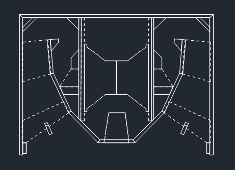 |
Replies:
Posted By: monkeypuzzle
Date Posted: 02 July 2020 at 4:13pm
|
Looks very interesting, rather than having a plate that covers the front ports as an optional, hows about a plate that is either blank or ported that swaps out in that front piece. This would allow access to do up those very hard to reach driver bolts. ------------- blah blah blah blah blah...... |
Posted By: madboffin
Date Posted: 02 July 2020 at 5:48pm
|
I like that. Go on then, take a leaf out of Doober's book and knock up a prototype! |
Posted By: snowflake
Date Posted: 02 July 2020 at 9:10pm
yeah might do that as it is going to be awkward. I'm going to make the whole baffle on which the driver is mounted removable, so I can put the mounting points where they are covenient to some degree.
|
 monkeypuzzle wrote:
Posted By: snowflake
Date Posted: 08 July 2020 at 1:18pm
|
I can get this driver to fit: http://www.loudspeakerdatabase.com/BMS/15N830v%C2%B2" rel="nofollow - http://www.loudspeakerdatabase.com/BMS/15N830v%C2%B2 can't quite get this one to fit but it seems to have been taken off the BMS website anyway:
http://www.loudspeakerdatabase.com/BMS/15S430v%C2%B2" rel="nofollow - http://www.loudspeakerdatabase.com/BMS/15S430v%C2%B2 |
Posted By: snowflake
Date Posted: 08 July 2020 at 1:23pm
|
few more details left and then try to make a sensible cutlist  |
Posted By: odc04r
Date Posted: 08 July 2020 at 3:22pm
|
Looks interesting, does resemble a certain design a little. How did you model it, port assisted FLH or variant on a bandpass horn? |
Posted By: snowflake
Date Posted: 08 July 2020 at 6:54pm
modelled in hornresp as FLH with ported rear chamber and a path length difference
|
Posted By: snowflake
Date Posted: 08 July 2020 at 7:03pm
|
one thing I'm really not sure about is the braces in the mouth. I've drawn them at an angle between the sidewall and the opposite horn flare. but if you assume the wavefront travels down each wall of the speaker at the same speed and is perpendicular to each wall, then the wavefront must be slightly S shaped as it approaches the mouth and the braces are at the wrong angle to allow smooth airflow past them. might replace with 6mm steel bar to remove the issue completely. once it gets to the mouth the path length differences should give quite a nicely curved wavefront coming out the front of the box. |
Posted By: odc04r
Date Posted: 08 July 2020 at 9:19pm
| Or just grind down the rear flat to make a wedge if you were worried. You'd imagine it probably wouldn't make a noticeable difference given wavelengths involved, but who can say till it is tried. |
Posted By: snowflake
Date Posted: 08 July 2020 at 9:46pm
|
I mean the wavefront must be something like this. so hitting that brace almost 90deg off from what you would want  |
Posted By: smoore
Date Posted: 08 July 2020 at 9:53pm
| How do you add a path length difference in hornresp between port and horn? |
Posted By: David McBean
Date Posted: 09 July 2020 at 8:38am
Calculate the combined power response then select the Tools > Output > Combined menu commands. Adjust the Path slider and press the OK button. Press F9 first if you want to permanently save the path value. In the Loudspeaker Wizard, select the Power, Chamber and Combined options and adjust the Path slider.
|
Posted By: bob4
Date Posted: 23 July 2020 at 8:31pm
Wow, nice one! I see flared ports 
|
Posted By: snowflake
Date Posted: 24 July 2020 at 9:06am
yes I have some of the 6" precision sound flares. two of those back to back gives about the right port length.
I'm tweaking the plans to get it out of two sheets of 8'*4'. means making the access hatch out of aluminium and losing a couple of braces. |
Posted By: snowflake
Date Posted: 25 July 2020 at 4:44pm
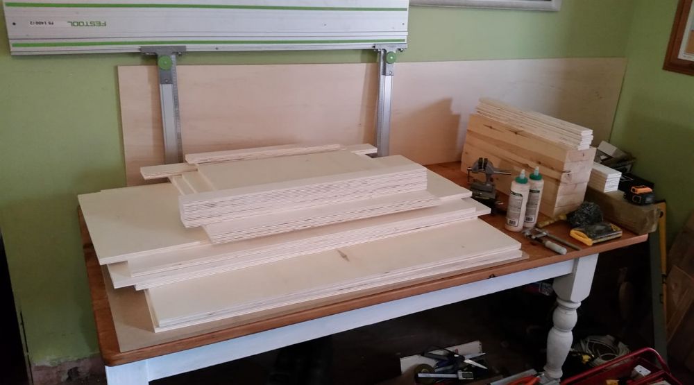
| it took a lot of tweaking but managed to lay it out onto two sheets of ply. will also need 4m of 44mm*144mm planed timber, 1m of 94mm*94m, 475mm*475mm aluminium panel (10mm or 12mm). will try and build it later in the summer. |
Posted By: snowflake
Date Posted: 04 September 2020 at 12:51am
|
B&C 15RBX100 also looks good for this and is half the price of the BMS 15N830v2 http://www.loudspeakerdatabase.com/BC/15RBX100#8%CE%A9" rel="nofollow - http://www.loudspeakerdatabase.com/BC/15RBX100#8%CE%A9 must get round to building a prototype!
|
Posted By: Teunos
Date Posted: 04 September 2020 at 9:15am
|
Have you considered how you are going to mount the drivers in this arrangement? Attraction/repulsion of the magnets will make assembly a pain especially if using ferrite drivers. ------------- Best regards, Teun. |
Posted By: DMorison
Date Posted: 04 September 2020 at 1:27pm
The RBX's are not in the current catalogue, so it may be that it'll become unavailable once current stock at sellers is gone.
|
Posted By: snowflake
Date Posted: 04 September 2020 at 1:28pm
| the whole driver baffle will be removable so I can mount the driver on the baffle before putting it into the speaker. bolts connecting baffle to the box can be positioned to make it easier to tighten the bolts. Rear panel and front panel are removable. I was imagining turning the box on one side and bolting down one driver, then flipping it 180 degrees and sliding the the other driver in underneath it and bolting it down. magents won't overlap that much but will only be 15mm clearance at one point. maybe I should cover the first with something if there is any danger of them attracting each other and chipping the magnets. |
Posted By: snowflake
Date Posted: 04 September 2020 at 1:49pm
|
with B&C 15RBX100 driver. theres slightly more clearance than shown as the edge of the magnet is angled. EDIT: looks like B&C have recently discontinued the 15RBX100 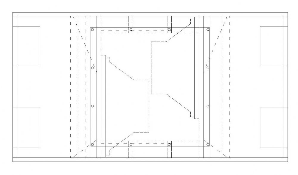 |
Posted By: snowflake
Date Posted: 14 September 2020 at 12:33pm
|
Beyma 15LEX1600Nd and B&C 15SW100 will both outperform the BMS and are cheaper. Confirmed they will fit after getting more detailed drawings with magnet dimensions.Also Beyma 15LEX1600Fe - slightly enlarged rear chamber so that it will fit with 10mm clearance between magnets. 15LEX1600Nd highest output, lightest 20mm clearance between magnets 373mm 15SW100 (8R and 4R) 10mm clearance 374mm bolts 15mm flange LF15X401 loads of clearance between magnets (no demodulating ring) 371-376mm 15mm flange 15LEX1600Fe cheapest to buy 10mm clearance 373mm 16mm flange inc. gasket 15TBW100 (8R and 4R) cheapest recones, heaviest, 5mm clearance 374mm 14mm flange LaVoce WAF154.00 and WAN154.00 (373mm) but not readily available in UK
|
Posted By: snowflake
Date Posted: 09 June 2021 at 10:33pm
finally building it 
 |
Posted By: concept-10
Date Posted: 10 June 2021 at 5:00pm
| Excellent news. Looking forward to it 😀 |
Posted By: snowflake
Date Posted: 15 June 2021 at 10:16pm
|
some build pics: throat flares. took three goes at the 3D trig to get these right. 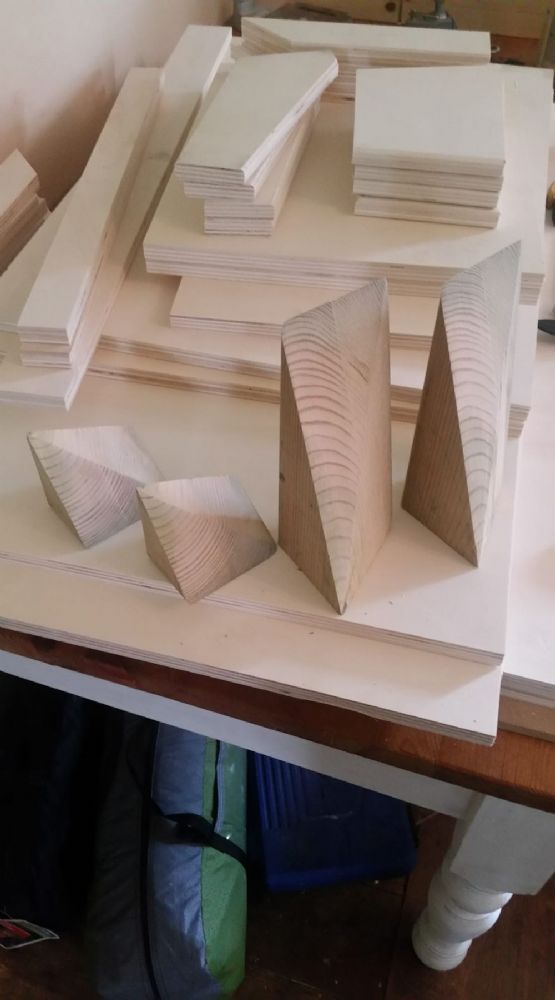 spline joint:  other pieces of wood to check for right-angle   |
Posted By: fat_brstd
Date Posted: 16 June 2021 at 5:09am
|
Look forward to seeing how this build goes, could be a very interesting box when it is done ------------- Melbournes Rootical Warrior Roots - Dub - Steppers http://www.facebook.com/adrians.wall" rel="nofollow - facebook page |
Posted By: djeddie
Date Posted: 18 June 2021 at 6:50pm
|
Yaaaaay! Someone's making sawdust!Looking forward to this one too. ------------- Chas n Dave : it's like Drum and Bass but with beards. E=mc² ±3dB |
Posted By: snowflake
Date Posted: 20 June 2021 at 7:21pm
|
first dry fit
  |
Posted By: snowflake
Date Posted: 28 June 2021 at 4:13pm
nearly there! 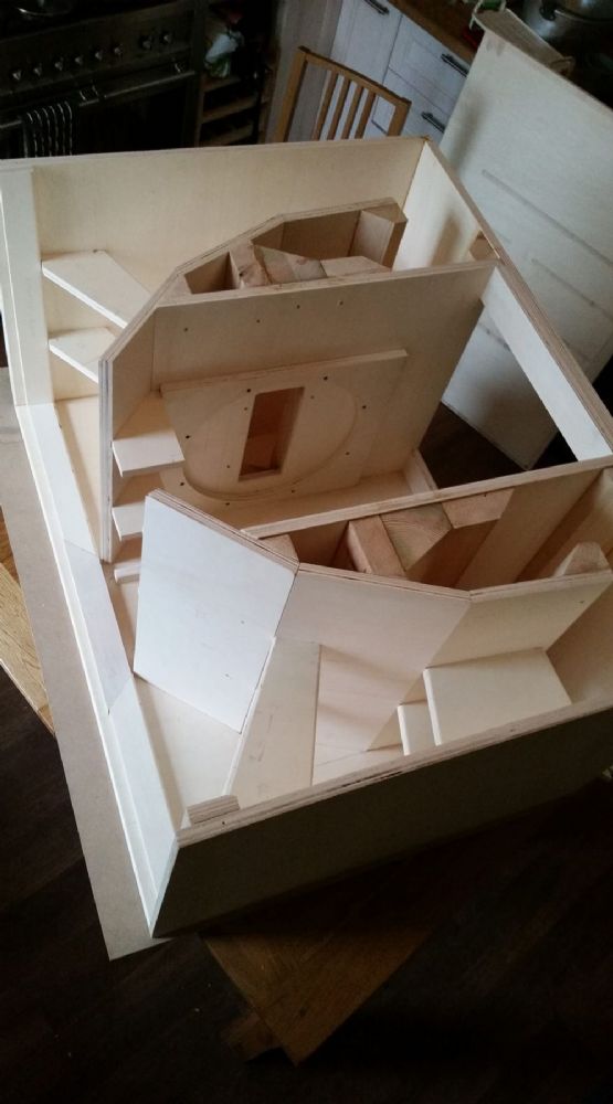  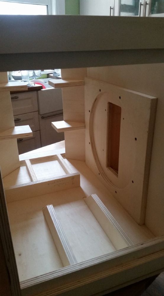 |
Posted By: smitske96
Date Posted: 28 June 2021 at 6:30pm
| Looks awesome! |
Posted By: Pinyorouk
Date Posted: 28 June 2021 at 9:00pm
| A work of art! |
Posted By: Contour
Date Posted: 28 June 2021 at 9:53pm
| Can you make some extra pictures to show the wood work at the offset driver throats? |
Posted By: snowflake
Date Posted: 28 June 2021 at 10:45pm
here's one of the baffles before they went in 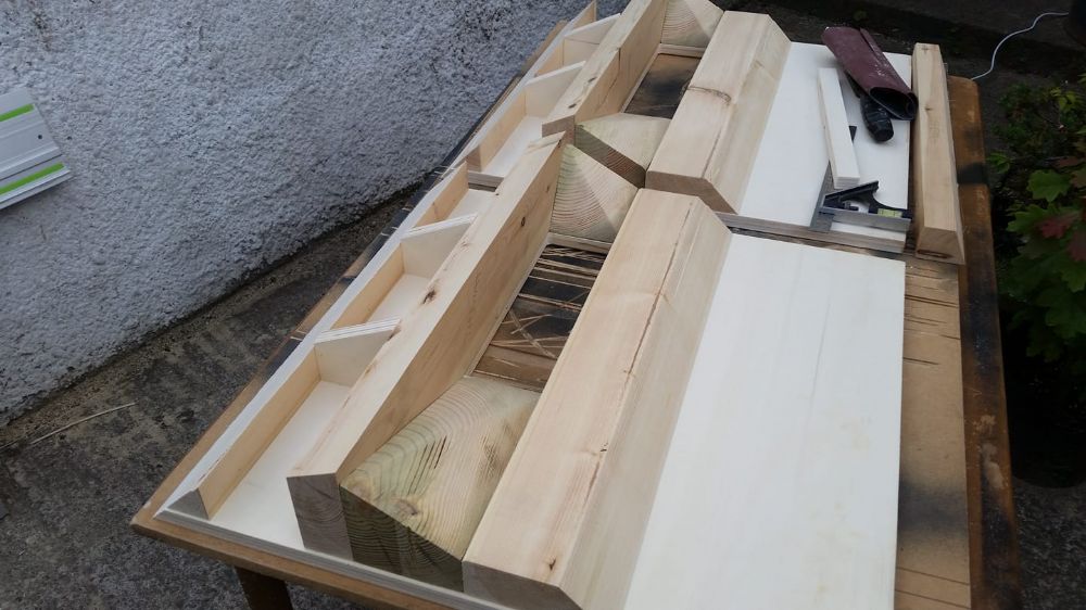 |
Posted By: cravings
Date Posted: 28 June 2021 at 11:11pm
| superb work |
Posted By: citizensc
Date Posted: 28 June 2021 at 11:44pm
|
Beautiful build, can not wait to see the results! ------------- https://www.facebook.com/voyager.system @voyager_soundsystem |
Posted By: hmaudio
Date Posted: 28 June 2021 at 11:56pm
 beautiful work snowflake! beautiful work snowflake! ------------- Nottingham based cab builder. https://www.facebook.com/HMAudio-154352667920145/?ref=bookmarks This account is used by 2 people. |
Posted By: jammin75
Date Posted: 29 June 2021 at 12:41am

------------- feel the vibes !!! "Who Feels it Knows it" Strong like Lion |
Posted By: imageoven
Date Posted: 29 June 2021 at 11:00am
|
Great stuff.
------------- Keep pushing on, things are gonna get better. |
Posted By: Bams
Date Posted: 30 June 2021 at 8:05pm
| That's some nice woodworking going on! maybe a stupid question but isn't it easier to make the flares out of layers plywood? |
Posted By: snowflake
Date Posted: 30 June 2021 at 11:23pm
I used 44mm*144mm planed timber and 94mm post for the throat pieces. otherwise would have ended up with many small pieces to cut and glue together which is difficult to cut with a rail saw, fiddly and time consuming to assemble, and the more joins you have the more likely it is one of them will eventually fail. Also I struggled to get it cut out of two 8*4 sheets and using some extra timber for these pieces helped. |
Posted By: imageoven
Date Posted: 01 July 2021 at 12:16am
|
Could you cut the timber sections with your rail saw then? I assume you have the Festool with 55mm (?) cut depth? ------------- Keep pushing on, things are gonna get better. |
Posted By: snowflake
Date Posted: 01 July 2021 at 1:19am
I had to do some cuts from both sides or finish off the last few mm with a hand saw. a band saw would have made things quicker. |
Posted By: imageoven
Date Posted: 01 July 2021 at 9:24am
Not easy. Good work. ------------- Keep pushing on, things are gonna get better. |
Posted By: snowflake
Date Posted: 08 July 2021 at 11:09am
|
good to confirm they actually fit into the rear chamber 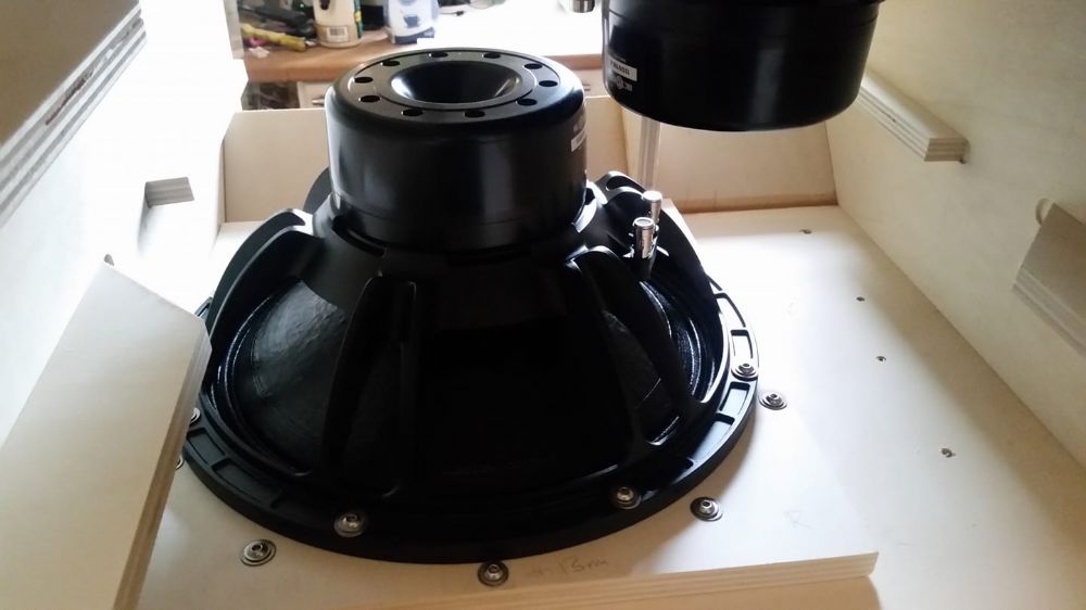 just need to glue the sides to the internals and fit the front and rear access hatches  shifted the drivers forward an inch so might even fit a battery in here!
 |
Posted By: smitske96
Date Posted: 08 July 2021 at 11:28am
| What kind of f3 are you targeting? |
Posted By: citizensc
Date Posted: 08 July 2021 at 11:43am
|
Is that a 15SW115??
------------- https://www.facebook.com/voyager.system @voyager_soundsystem |
Posted By: KDW32
Date Posted: 08 July 2021 at 12:30pm
|
Loving this thread
|
Posted By: snowflake
Date Posted: 08 July 2021 at 3:30pm
should do 50Hz - possibly a bit lower if my idea of using a hole in the wheelboard for additional loading works. They are 15SW100. The 115 would have been nice but no way to make the magnet assemblies fit. Would have used the Beyma 15LEX1600Nd but they weren't in stock and are significantly more expensive.
|
Posted By: Teunos
Date Posted: 09 July 2021 at 3:56pm
Premium quality build, keep up the good work and thanks for taking the time to post pictures . .------------- Best regards, Teun. |
Posted By: snowflake
Date Posted: 28 July 2021 at 11:31pm
did some outdoor measurements today except red all are 2.83 volts into nominal 4R load (2 8R drivers in parallel) 1/3 octave smoothing
blue and purple are 1m on axis and 1m rear (20cm behind 80cm deep box). speaker lying on its largest side. mic on small stand approx 10cm from ground. green is average of blue and purple plus two other off axis measurements so should be an approximate power response - all taken at 1m though so maybe underestimate orange is average of two 1m measurements of speaker pointing toward ground but spaced up on bricks 22cm from ground red is 28.3V at 10m on axis -3dB seems to be about 60Hz. upper roll off is better than predicted. rear access hatch is currently 12mm ply with a couple of braces. using 12mm aluminium might change the q of the rear chamber a bit and improve the low end. |
Posted By: snowflake
Date Posted: 28 July 2021 at 11:43pm
|
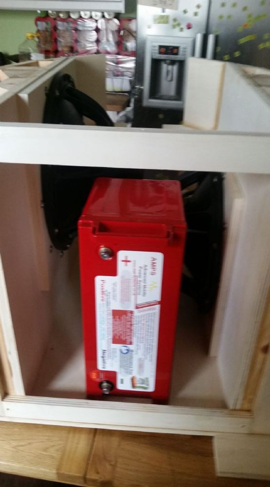
forgot to take many more build pics. here is one of the rear chamber. very well braced now with aluminium to mount the battery for portable system use. 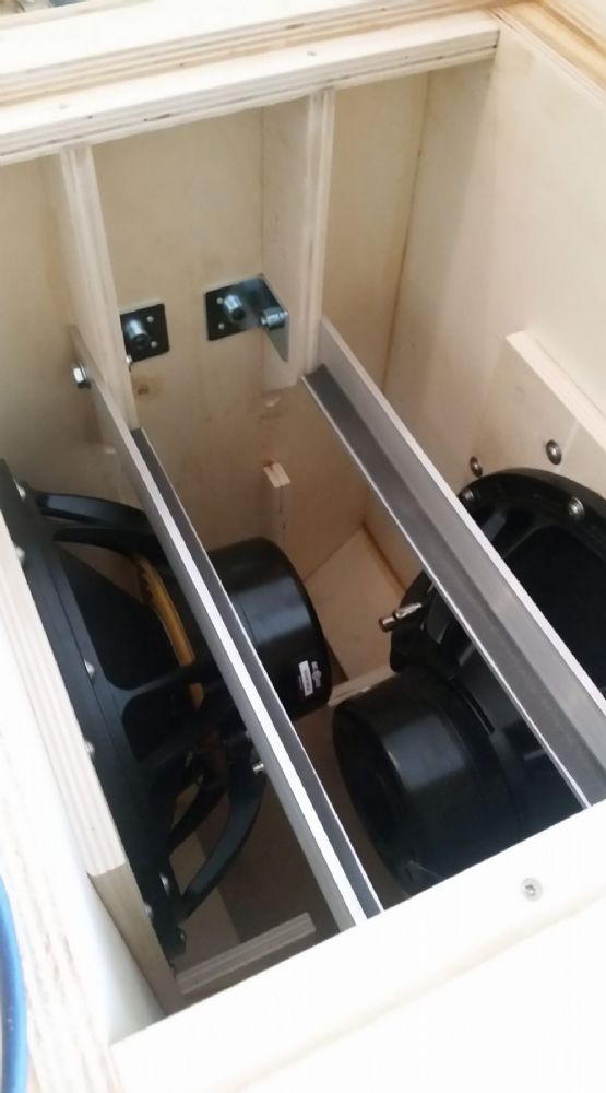 battery just fits with 2mm clearance. If I rejigged things a bit could get the amplifier in the rear chamber too, mounted on the rear access hatch. 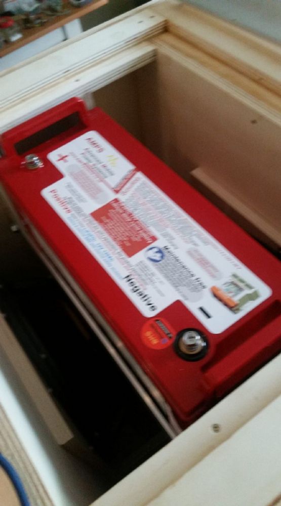 |
Posted By: imageoven
Date Posted: 29 July 2021 at 12:32am
|
What is the battery / amp set up (proposal)? - sorry if Ive missed this. ------------- Keep pushing on, things are gonna get better. |
Posted By: toastyghost
Date Posted: 29 July 2021 at 1:16am
Interesting sets of measurements, but I’d suggest caution before reading too much into the data. From quite a lot of experience with ‘similar’ boxes and horns in general, you’re measuring too close to be getting reliable data. The radiating area is quite large in relation to the distance of the mic, and you’re likely still ‘inside the horn’ acoustically. 10 meters is ideal but 4 meters is also sufficient in most real world circumstances, and has the benefit of being easy to compensate back to a 1 meter level via extra drive voltage or simple inverse square law maths. A quick check for this is the blue and purple traces. If you’ve actually managed to achieve a 10 dB front to rear rejection when equitemporal/equidistant from the acoustic centre, then you’re beating the full size product that inspired you - and some cardioid designs - by quite some margin. Have you tried covering the ports to determine their influence on the overall response? The shift in rolloff shape at the low corner for the red trace might indicate that the ports are creating some phase cancellations. The good news is that I would expect better results i than you’ve got even now, and you can likely ditch the 1/3 smoothing as there’ll be fewer ripples in the response to boot. |
Posted By: snowflake
Date Posted: 29 July 2021 at 8:53am
Banda Elite 4000.4 amp Sterling 120Ah lithium battery final system will include Waves Maxxbass 103 to simulate some sub-bass content t.racks DSP 4x4 Mini for crossover.
|
Posted By: snowflake
Date Posted: 29 July 2021 at 9:07am
I haven't turned it into a ported horn yet. wanted to measure it a flh and possibly as a mass-loaded horn first and then compare the addition of the ports. I did one measurement at 28.3V @10m and would like to do them all like that but we heard shouts of "what the f*** was that from other people in the park". Maybe 11.3V @ 4m (+12dB) won't cause too much commotion. don't know why I didn't try without the 1/3 smoothing will also try and get some battery current readings playing some music material.
|
Posted By: snowflake
Date Posted: 29 July 2021 at 9:34pm
|
more measurements shown with 1/48th smoothing: cyan 28.3V 10m measurement from yesterday green 11.3V@4m on axis blue power response average of eight polar measurements red average of two measurements with speaker facing down at ground. orange 11.3V@4m 180 deg off axis - this is the measurement that changed very significantly and the front to rear rejection @100Hz is therefore closer to 6dB than 10dB taking average power response as 107dB it is 3dB down at 55Hz and 330Hz
 |
Posted By: fat_brstd
Date Posted: 30 July 2021 at 12:57am
|
Looking great, how does it sound around the 200hz region? Any honkiness or is nice and smooth? ------------- Melbournes Rootical Warrior Roots - Dub - Steppers http://www.facebook.com/adrians.wall" rel="nofollow - facebook page |
Posted By: snowflake
Date Posted: 30 July 2021 at 11:59pm
sounds pretty good. listened to some motown stuff and even with it crossed at 300Hz the vocals didn't sound too muddy. this is the on axis distortion plot with 28.3V 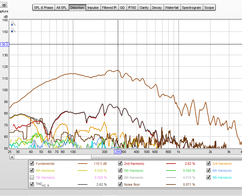 |
Posted By: snowflake
Date Posted: 31 July 2021 at 12:02am
SPL and phase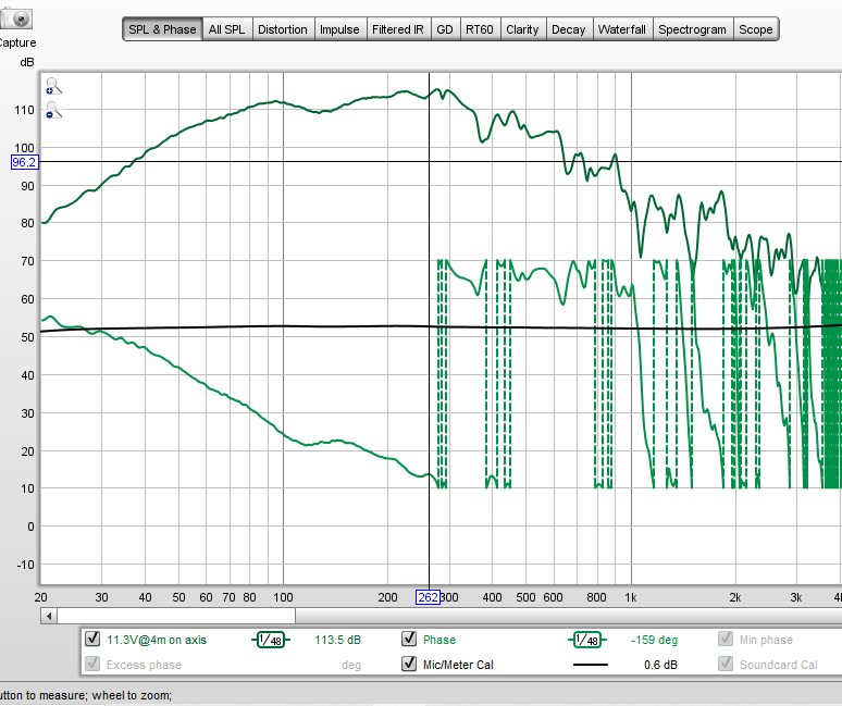 |
Posted By: snowflake
Date Posted: 31 July 2021 at 12:06am
group delay with 1/3 smoothing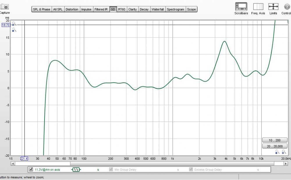 |
Posted By: toastyghost
Date Posted: 31 July 2021 at 12:41am
|
Excellent work! That's more in line with what I'd expect from a design with this much thought into it. <6 dB from >100 Hz won't win any medals in PA land, but it'll probably get you a couple hours extra fun off a battery with some friends in a field. I'm curious what led you to the measurements with the horn facing the floor? It's not a technique I've seen before. |
Posted By: snowflake
Date Posted: 31 July 2021 at 9:26am
I'm going to use it as a mobile system with 360deg dispersion. top unit will be 360deg too. going to try a wheelboard with a hole in it next. thinking it will provide some loading and increase the effective horn length too. will be using 8" wheels so will have space underneath to put a lot of bracing on the wheelboard. I was hoping the speaker pointed down would have performed a bit better even without the wheelboard. 22cm (red) was better than 11cm (purple). maybe even slightly higher would be okay. I've found some nice 8" castors so will get those and then try the BC style loading and see if I can get any extra low extension. EDIT: 8" castors have a height of 26cm, 10" castors have a height of 32cm. so I will do some more measurements before deciding which to try.  |
Posted By: snowflake
Date Posted: 14 August 2021 at 1:58pm
|
weighed the finished speaker yesterday - cab is 72kg but will probably go up to 75kg with some paint and a few handles added. It is mostly poplar which is lighter than birch and not quite as stiff but it is well braced where it matters and doesn't seem to resonate (except for the rear access hatch which I am going to replace with aluminium). for it's weight the max output is pretty impressive. battery is 15.5kg amp is 5kg wheelboard is 12.5kg (still playing with this to get flat response by adjusting opening size) top box will be about 20kg it rolls very easily on the 8" castors I got, even on rough ground, and they don't rattle too badly
|
Posted By: toastyghost
Date Posted: 14 August 2021 at 3:46pm
|
Just a heads up if you’re going to try the ‘choke’ of a BC style opening - there needs to be significant space in front of the cabinet for the modified wavefront to develop. It’s about 45 centimetres for the BC415. The rest is all down to the expansion and CSA of the internal horn so that it can ‘see’ the opening and the ‘virtual horn’ on the boundary. I’m not sure it’s a good idea if you’re after 360 coverage, since the entire point of the BC design is to improve on axis sensitivity through focusing of the sound output via the ‘cancellation donut’? There’s an install of a BC415 in Anomalie in Berlin that’s flown central aiming down, and I’m told that it was tricky to integrate with the four point mains since there is almost no bass once you get close to the edge of the dance floor. If you want omnidirectional output then perhaps inspiration from the Apple HomePod’s horn loading would be a good thing to include in the wheelboard? https://www.diyaudio.com/forums/multi-way/308654-apples-homepod-bottom-firing-horn-provides-directivity-control.html" rel="nofollow - https://www.diyaudio.com/forums/multi-way/308654-apples-homepod-bottom-firing-horn-provides-directivity-control.html Lots of drawings in the patents. |
Posted By: snowflake
Date Posted: 14 August 2021 at 4:19pm
|
yeah I could tell it wasn't quite working as hoped. I have got more output below 55Hz from a hole that is 1/3 of the horn mouth - dropped the f3 from 55Hz to 42Hz. but it comes at the cost of ~3dB sensitivity from 60-120Hz. running off battery I would rather have the sensitivity. could have gone up to the 32cm wheels - Will try that and see what happens. I'm not sure the dimensions of the cab are big enough to get an effect though, even using the ground as a boundary. I think if I make the hole bigger I might find a sweet spot at about 60% of the horn mouth where it smooths out the 2dB peaks in the response and gives me a few Hz extra bottom end whilst only losing <1dB sensitivity. will also try and find a brick corner somewhere I can use to measure 1/8th space response and see how low it goes. I think a stack of four or more of these FLH could be quite impressive for PA use. I haven't tried venting the rear chamber yet either.
|
Posted By: toastyghost
Date Posted: 14 August 2021 at 5:49pm
That suggests the ratios aren’t correct for the BC loading, and instead you’ve got an ‘inverse horn’ effect where the throat is larger than the mouth. That type of design gets much broader frequency response at the expense of sensitivity, but that’s the opposite of the boundary loading effect you observe when going from ‘normal’ FLH to BC mode in adaptable boxes like the BC218 and BC215.  Still nice to have the option though, depending on the event / music type. Personally I prefer a lower playing system at lower level than one that’s hammering it out with no LF. |
Posted By: snowflake
Date Posted: 14 August 2021 at 6:16pm
|
I really need to do some impedance measurements because the lower sensitivity I am measuring doesn't necessarily mean lower efficiency which is what will drain the battery. I will try some Hornresp sims to see if I can get an idea how impedance changes. I also have the option of using a Waves Maxxbass 102 processor - its lower setting is 60Hz which is where the speaker starts to roll off. |
Posted By: toastyghost
Date Posted: 14 August 2021 at 6:30pm
|
Hornresp can’t simulate diffraction so as yet I haven’t seen anyone get boundary sims out of it in a meaningful manner. You can export the data and combine it manually with something like Edge Tolvan or Jeff Bagby’s spreadsheet if you’re clever about it. Or it’s Akabak time… |
Posted By: snowflake
Date Posted: 15 August 2021 at 2:26pm
oh yeah I've used Bagby's spreadsheet before. but any diffraction will change the directivity but not the impedance won't it? and as you say I'm possibly not even getting a diffraction effect here - so could just model the hole and the external horn path in hornresp.
|