BC horns from standard FLHs
Printed From: Speakerplans.com
Category: General
Forum Name: General Forum
Forum Description: Open Discussion / Questions
URL: https://forum.speakerplans.com/forum_posts.asp?TID=105665
Printed Date: 27 March 2026 at 4:06am
Software Version: Web Wiz Forums 12.08 - https://www.webwizforums.com
Topic: BC horns from standard FLHs
Posted By: citizensc
Subject: BC horns from standard FLHs
Date Posted: 03 September 2020 at 4:27am
|
Hi all Just continuing a conversation from another thread: https://forum.speakerplans.com/bg-horn-mk1-36hz-front-loaded-horn_topic105410.html" rel="nofollow - https://forum.speakerplans.com/bg-horn-mk1-36hz-front-loaded-horn_topic105410.html Here are some sims of 4 standard BG horns and 4 BG horns with a hole cut in them to form a BC horn. I think the results are interesting, especially to anyone trying to reach the low 30s with a FLH. There was no science involved in my decision making with regards to the size, location or shape of the hole in the BC horn. I just kind made it look 'right' in my mind. In retrospect I think it may need to be larger. I guess if I try that and compare the results, that's when it becomes science. All sims are in 2pi, 1.41v @ 2 ohm, measured from 10m with values scaled to represent a measurement from 1m. Image of how the standard BG horns are simmed.  Image of how the BC horns are simmed.  Red=BC, Blue=standard BG  BG directivity  BCBG directivity  I think these results are interesting, solid 5hz more extension is nothing to ignore. I suspect with a larger hole, it may have slightly increased efficiency. Let me know what you think. If you want me to try anything let me know! |
Replies:
Posted By: mobiele eenheid
Date Posted: 03 September 2020 at 5:46am
|
It's definitely interesting, some thoughts.
I've measured quite a few horn extensions myself, some followed the sim accurately, some behaved really different somehow. I suspect that is because of the large steps in effective surface area and different behavior to what the mind thinks the air path will be like. I would measure it and then correlate the simulation to the measurement. Long way of saying, simulate, build, measure, repeat. |
Posted By: KaphaSound
Date Posted: 03 September 2020 at 7:36am
| Nice work, how did the final result here stack up against hornresp? From what I’ve been seeing Akabak seems more defined but the larger fluctuations in spl are very similar. I definitely still think 2 pi isn’t the most accurate with a face that large. Even if only 40% of the wavelength is diffracted the directivity gains there will still be noticeable, but especially in the higher sub frequencies you’ll see some extra sensitivity. My main concern now with this type of horn is group delay. Also from reading some of Danley’s comments he said the trick is in something along the lines of trying to best couple the flare rate to the flat face at the mouth (which I think just means having a slow enough increase in cross sectional area to best suit low frequencies while still expanding fast enough to almost be completely flat at the end of the horn). It’s a tricky beast, but done right I still think this design is the future of bass horns. |
Posted By: Jo bg
Date Posted: 03 September 2020 at 10:13am
|
The idea for the Boundary coupled woofers like the 415 is that the hemispheric mouth “bubble” is actually bounded by the 60 by 60 inch flat baffle but in order for that to couple to the interior horn, the interior horn has to have an end area large enough to provide something close to the needed expansion rate to mate up to the exterior expansion. At the low end, the exit hole is a minor effect compared to the radiation resistances. The up side is whatever the acoustic gain is by that coupling AND the acoustic energy because of forward directivity which reduces the spl going to the rear. Keep in mind your talking about a subwoofer where 4 or 6 would be used in a large football stadium and ones and two’s per side for loud EDM events, not a home speaker unless one wants to dry their hair with it;
The Mouth does not need to be as big as the last part of the throat, following traditional horn terminstion rules, as the real termination is the air bubble contained by the flat baffle, this comes fromt the Bc creator voice... at lower Wl the mouth is not seen and the important thing is continuity between throat and exterior. At higher and smaller Wls where the mouth is seen the size is enough from what I understand. Interesting threads on diyaudio about Bc and its predecessor Bdeap from some years ago. Nice threads lately, this place seems more lively thanks!
|
Posted By: doller
Date Posted: 03 September 2020 at 10:24am
|
Sorry citizens sir I didn't get back to you regarding the labs. I am thinking of junking them so not a big waste to cut a hole in them. First problem is I have no idea how big the hole should be. How does it relate to fs? I need to put two together and measure the sq mt idge. Next is to do a plot outside rite now would be impossible. I could do one in the workshop but what would it mean? Two labs standard and two labs bc. But as I said inside measurement. I would get wholey flamed for that on this forum. As always good work sir. Remember four labs stacked like that would be 2.4 mtrs high, about. not possible I think two at a time.
|
Posted By: citizensc
Date Posted: 03 September 2020 at 11:25am
This sim takes things in to account the same way, putting the cab on the ground in a big open field and measuring them does. By 2pi, I mean its sitting on an infinite plane rather than floating in space. The mic array is set up in a 10m arc, 10cm off the plane.
aahaha, I cant unsee that now.
If you look at that hole, then divide it by 4, the cross sectional area per cab is actually really small, <25% of the mouth area of a BG horn. If I make it ~40% of the cross sectional area, it might shorten the horn by 50mm but I doubt that will have a tangible impact compared to not properly coupling with the exterior of the cabs.
What simulation software did these simulations use? I am not saying AKABAK 3 is perfect or even that I have mastered it but it is special when compared to other software used by the DIY community. It doesn't just simulate a straight horn path, that approximates a folded horn. It simulates the actual 3d model of the horn, including the exterior panels, the shape of the driver diaphragm, all the folds, any mistakes made when folding the horn in the design phase. Maybe these sims wont perfectly overlay a real life measurement but I have some confidence that they will tell you what the impact of a change is. Eg. the BC arrangement in my above post does not improve efficiency buy does improve LF extension.
If you look in the BG horn thread, the sims there reflect this sim to a much greater degree than I was expecting. They seem to tell a similar story, increased extension with a peak in sensitivity at ~35hz
As far as AKABAK 3 goes, by 2pi, I just mean its sitting on an infinate plane. AKABAK 3 takes the exact dimensions of the exterior of the cab in to account. I dont think the halfspace/quater space discussion is relevant here as I can just model it as if its the real world cab sitting on the ground. Are you referring to the Danley quote Jo bg posted below?
This makes me think you cant just do this to any FLH, horns with high T values may work better as the expansion rate at the end of the end of the horn will be higher.
I think there has to be a limit on how small the hole can be before it impacts efficiency and coupling. You cant put 145dB of bass through a hole the size of an orange with out it liming the amount of energy that can pass through, and I have a hard time picturing that wave coupling to a 2m x 2m baffle. Tomorrow I am going to do some more sims, might try 3 different sizes and overlay the graphs, when I get the right size, I might try some different shapes. I will also do a visualisation of the sound pressure at the mouth, maybe we will be able to see if its coupling.
Thanks for the support, it is nice to know other people are interested in what I am working on. I'm in one of the worlds toughest lock-downs, away from my home city so I don't have a lot of better things to do with my time.
I am going to do some experimentation with hole size, if you are interested I may build a labhorn model and try it. I am also interested in what would happen if you did this with two horns, with the horn mouths on the ground. Would it still work? I might sim this too. Sorry for the wall of text guys! |
 mobiele eenheid wrote:
Posted By: bass*en*mass
Date Posted: 03 September 2020 at 10:48pm
|
if you compare the bc218 measurements you`ll see that the bc config adds little to the low corner compared to the gain in directivity due to the `boundary`involved?! :)
|
Posted By: citizensc
Date Posted: 04 September 2020 at 6:04am
|
I did some experimenting with cutout size. Cross sectional area is in the key down the bottom. Seems a larger hole results in better sensitivity but increased low corner. This makes sense to me as the horn is getting slightly shorter but the hole is less restrictive.  This is 4 standard BGs in a standard config compared to the largest cutout. About 1dB improvement in sensitivity and 3hz lf extension.  Here are some top-down view maps of pressure at 63hz Standard BG  BC 1110cm^2 cutout  BC 1400 cutout  BC1765 cutout - Key got a little messed up on this one, the values are correct, colours are just shifted.  I am thinking the BG horn is not a good candidate for boundary coupling, the pressure maps above show the standard BG horn to radiate from the whole mouth. The BC horns have a hot spot around the cutout but this reduces by ~9dB at the edge of the baffle. The 15BG100 is a relatively high Qts, this means to achieve reactance annulling via the method layed out in the letters to the editor section of the Leache paper, you need a high T-value. High T-values do not have fast flare rates at the mouth of the horn. If I find the motivation I might try to design a dedicated BC horn using the 15SW115 or even the 15DS115 then repeat this analysis on it. Let me know what you think, does my hypothesis make sense to you? |
Posted By: KaphaSound
Date Posted: 04 September 2020 at 6:59am
| Yea love this, I’d say definitely a driver with a lower qts more suited for horns would be a better shout. Also it looks as though maybe the peak spl from those radiation graphs shrinks closer to the mouth but the 3rd range or so in actually might increase in area. Just another factor to consider. I know the original purpose of this project was to use a 15” driver and I’d say very convincing results have been achieved, but I’ve slowly become more convinced that the marginal returns are seriously worth looking at with 18”s. Either way though, my bet is a lower qts will significantly help out here. |
Posted By: bob4
Date Posted: 04 September 2020 at 8:01am
Wow, top contribution citizensc!!!!  Very encouraging results. I see hypercardioid dispersion patterns for the BC version Very encouraging results. I see hypercardioid dispersion patterns for the BC version 
Instead of trying to achieve a 2x2 array, it would be easier to just have an horizontal array, place the horns with the mouth downwards and have the aperture on ground level.
|
Posted By: citizensc
Date Posted: 04 September 2020 at 10:36am
Its not that the 15bg100 isn't suited to horns, its the ideal driver for getting a cab of that volume to play as low as it does. On paper the qtc of the system (the horn + the driver) is about 0.4, making it critically damped. The issue is that the geometry of a horn designed for it isn't ideal for boundary coupling. In the below image, you can the impact t-value has on the shape of curves, imagine those curves as the walls of a horn. The lower the t-value, the higher the expansion rate at the mouth of the horn. The goal is to have an expansion rate high enough to allow the waves to mate with the exterior of the cab... or at least that is my thinking.  taken from:https://www.grc.com/acoustics/an-introduction-to-horn-theory.pdf
|
Posted By: citizensc
Date Posted: 04 September 2020 at 10:38am
| whoops, double posted by mistake... |
Posted By: KaphaSound
Date Posted: 04 September 2020 at 5:47pm
| Citizensc thanks for the info you’ve been incredibly helpful! What exactly is the t-value representing? Given that last graph it certainly looks like a low t (assuming qts) would be best for a BC horn. This must be partially why Danley and Ivan Beaver say it’s not necessarily about using the most powerful driver in the BC designs, but rather a driver that best suits in other parameters. Have a couple ideas I’ll model/post soon! As for the labhorns it looks like the lab12 also has a fairly high qts but I’d still be curious what extension could be added there. |
Posted By: KaphaSound
Date Posted: 07 September 2020 at 2:38am
| The B&C 15NW100 looks like a great fit from an initial glance. Qts of .22 and total EBP of over 140. |
Posted By: citizensc
Date Posted: 07 September 2020 at 10:12am
| I think I will go with the SW115 or DS115, if you want max output from 4 cabs (why else would you build a BC horn), you would likely want a lot of power handling. Right now I am leaning towards the SW, the paper snowflake linked https://forum.speakerplans.com/hyperbolic-bass-horns_topic105331_page3.html" rel="nofollow - here suggests that building a super low T horn is not a good idea. Designing a horn around a driver with super high BL like the DS115 without a very high compression ratio, ripple and low T seems difficult. I will give both a try though. |
Posted By: doller
Date Posted: 07 September 2020 at 10:14am
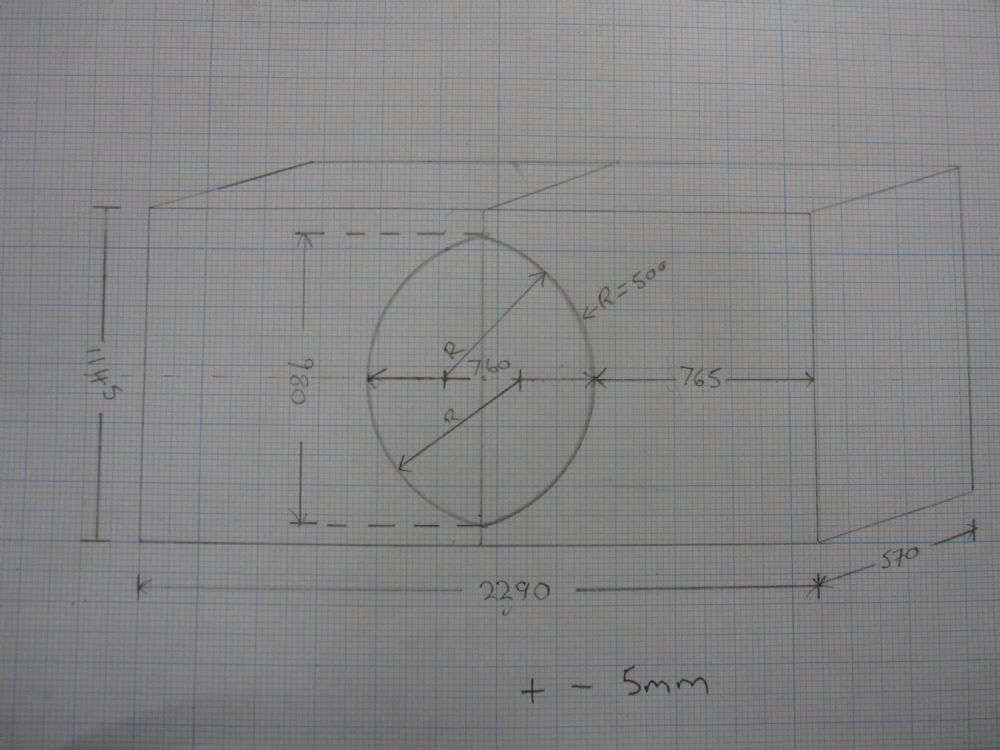
|
Posted By: doller
Date Posted: 07 September 2020 at 10:26am
|
That is what would be possible with the labs. The biggest size you could cut out on the edge of the horn flare. I was thinking of stacking them like that same as the Danley. If it would work or not I have no idea. I am sorry for the pencil drawing but it was quick and I am very busy rite now. Maybe we are missing the point a bit here I don't think that it is about gaining spl and extension so much. Modern speakers are pretty bloody loud as they are. The point for me would be directivity I am interested in how that would sound. Because the bass would be more focused would it sound louder, cleaner? am I wrong in thinking that the Danley are less omnidirectional? More energy focused on the dance floor. Less wasted. |
Posted By: KaphaSound
Date Posted: 07 September 2020 at 4:27pm
| Yea I think directivity is a big part of it but with directivity comes extra sensitivity and extension if I’m not mistaken. I could also be completely wrong here but my incentive for making a BC horn is less about spl (considering these things max out beyond 140db which I will never want to subject anyone standing in-front to) and more about the size of the wavefront/tactile sensation. Again I could be wrong but in order to spread as much sound/weight as these BC horns you’d need like 4 or more double 18s to match the size of the face or a bunch of scoops or other horn designs just because of the conventional orientation of the mouth, and while I know this isn’t scientific at all I always find that standing infront of stacks of subs with a large mouth area/surface area comes with a much more visceral tactile sensation even at similar volumes. |
Posted By: doller
Date Posted: 08 September 2020 at 10:06am
| agree 100percent kapha extension and spl would be a bonus. You could be very correct in thinking that 18's would be better. labs are great speakers but they need to be stacked high to get the wow effect. Like you I wouldn't want to subject people to 140db continuous. It's silly 139 is plenty. LOL But yes I have never heard the Danleys or the lambada labs. Really want to. |
Posted By: Jo bg
Date Posted: 08 September 2020 at 12:35pm
|
Nicest thing about a 140dB capable system is that you can do 130dBs at 1/10 of rated power, keeping the drivers happy and cool in the linear zone, minimizing power compression and distortion and maximising dynamics by allowing quick transients to pass uncompressed. It will sound effortless and clean compared to a 130dB system pushed to the max. And last longer.
|
Posted By: Contour
Date Posted: 08 September 2020 at 3:05pm
| Instead of cutting the eye, with possible risk to ruin your cab, perhaps you can reach same effect by placing the cabs front to front and then give bit of splay. Piece of board on top to close the v shaped gap. With different splay you can test optimal area of the eye...? |
Posted By: KaphaSound
Date Posted: 08 September 2020 at 7:50pm
|
Jo bg agreed 100% here. I'm quite new to this, but initially I was planning on just picking up a Behringer NX6000 for one of these designs because I always read headroom will improve the sound, but would I be fine or better off with a much more trusted brand like Crown or QSC putting out only 1000 watts total to 2 paralleled 8ohm drivers for a total of 2 4ohm loads? In other words what would be better a trusted brand with less headroom or Behringer with more headroom? Because I also thought I've read that not enough power can do damage as well, but with these designs I can't fathom needing to run them anywhere near full power rating for the types of gigs I'm planning (maybe 200-500 people), especially considering hornresp is telling me I'm approaching 130db with only 80watts through 4 drivers??. Anyways here's some hornresp charts for the 15NW100:     So an f3 of 33hz or so in 2pi and considering that some directivity should be taken into account we can assume a bit lower with some increased sensitivity. Group delay also looks good with about 25ms in the 30-100hz passband. The EBP of this particular driver is around 140 or so which may have to do with the reasonably tight group delay? Other reasons for choosing this driver were definitely cost and weight since the idea here is to make it portable with 2 people. Let me know any thoughts; looking forward to seeing citizensc's sims with the other B&C drivers as well! Now to just figure out how to fold this thing...
|
Posted By: Jo bg
Date Posted: 09 September 2020 at 12:15pm
|
Could you post impedance and excursion too? With 10 cm backchamber are you putting magnet in throat? You are not powering a heater with 80w continuous, music is dynamic, you have to allow for short peaks and transients that will require higher power , so in practice you will need way more if you don't want to clip amd compress. While they could be called the heart of the system, until you take them to limits (and hear the sound of limiters), amplifiers are the less important part in sound quality. Once you've got nuff voltage and a decent power supply, difference will be minimal compared to difference other parts of the system could make. A good quality driver, in a fitting enclosure built with proper ply and bracing, good processing and gain staging, will make an enourmous difference compared to difference in amplifiers, as long as those are operated within their limits. So in your case i would go with a new Berry with warranty, you will have double the power, instead of (usually overpriced) heavyweights with uncertain history and more failure probabilty. Unless you are going to rent or host a lot of events on this, then you may look for something more reliable and many times more expensive. But berrys are very good for beginners, warranty gives you 3 years of peace of mind. And new ones are way less ugly than the inukes i bought. Those served me well for almost three years until i upgraded to labs, but at 8 times the price , and more for added reliability and rentability than sound quality. There is an improvement but not overwhelming. |
Posted By: Jo bg
Date Posted: 09 September 2020 at 12:37pm
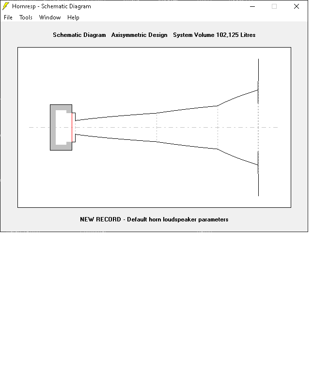 you could try and sim the boundary by disjoining segments; double click on s1 (will turn red) will allow to input different values for s4 in the last two segments, allowing to simulate the abrupt change. you could try and sim the boundary by disjoining segments; double click on s1 (will turn red) will allow to input different values for s4 in the last two segments, allowing to simulate the abrupt change.a very short (0,1) last segment with s4 the size of the eye and s5 the size of the front will approssimate the flat front.
|
Posted By: KaphaSound
Date Posted: 09 September 2020 at 3:05pm
The values put for VRC and LRC were largely based on citenzensc's BG horn calculations. I believe LRC is the average length from the driver within the rear chamber of 50 liters. To be honest I haven't folded the horn yet but I have an idea of what I'm going for and will adjust parameters accordingly, but playing around in hornresp changing the VRC/LRC by 10-15 didn't seem to have much of an effect other than in the high frequency resonances. Here's displacement and impedance for now, I'll have a look at simulating the face as well.  As for the amp question thanks for the info! I still would guess though that running 400watts out of an amp that's capable of 1000 could be enough headroom to not be concerned about clipping at the peaks? At that point you start to run into displacement issues anyways at about 34hz at 134db, a level I most likely also will not be pushing considering that 116db was about the strongest bass I've felt on a funktion rig measured with the DecibelX app on an iPhone (so not super accurate but maybe not horribly off) and that was approaching uncomfortable for sure.
|
Posted By: KaphaSound
Date Posted: 09 September 2020 at 3:35pm
| So I just experimented with splitting the S4 and using S5 as the face but I don't think it's a good approximation because you can basically set the S4 throat area to 1 or to 8000 and it doesn't change the sim at all. The results were certainly worse by about 5hz in the F3, so I'm hoping that method isn't very accurate. I'm completely speculating that you could just assume the face of the stack is like a wall somewhere between 1 and 2pi as if you mounted a horn flush directly into it, but perhaps citizensc can grace us with some Akabak charts for more accuracy. |
Posted By: Jo bg
Date Posted: 09 September 2020 at 4:02pm
|
Your phone was clipping, you need a good mic to measure at high level, 116 db of bass is nothing to write home about , if you remember it as heavy it was way louder.
Try put an hipass filter with filterwizard and drive it with a sensible voltage to get a feeling of real world excursion. Impedance plot is n9t very readable, can you post 1 speaker with a readable scale (you can change it in options) ? Seems a waste of driver if you can push only 400w into it. Seems a rating for a 70s sub... |
Posted By: KaphaSound
Date Posted: 09 September 2020 at 5:31pm
Here's the impedance of one driver/horn Here's Max Spl  Now here's where I have a question. Does adding a high pass filter really reduce displacement by this much? It seems like for such a modest reduction in SPL you gain big reductions in displacement. Also note that I used the xmax of 9mm instead of the xvar of 11mm which B&C suggest may be a more accurate measurement.   Back to the amp, I know it would theoretically be a waste considering these drivers can handle 1000 watts rms but again I can't fathom needing even 130db for 200-500 people. I also used my phone to measure infront of Mungo's Hifi stacks and that was some chest thumping bone rattling bass coming in at 108db which makes me think maybe 116 might be the limit but I'd assume the Mungo's measurement could still be ballpark.
|
Posted By: Contour
Date Posted: 09 September 2020 at 5:44pm
| A scale versus C scale measurements? Big difference... |
Posted By: Jo bg
Date Posted: 09 September 2020 at 6:05pm
|
Yes weighting and time constants need to be taken in consideration... and anyway i doubt an iphone mic is reliable at that level, again. If 108 had been a reliable measurement, it would have been averaged over a long time, and you can see differences like 20 dBs between peak dB recorded and the average. The speaker needs to provide for the peak, so your 108 dB measurement could contain 128 dB peaks....  Op should not base ANY assumption on that numbers, even if measurement were reliable they need context. I am really the only one thinking that 108db or even 116 in front of a big stack (a fast measurement with a meaningful weighting, not A, something you can relate to Hornresp dBs) is not loud at all ? Heck we are in 12v territory, not big stacks. About hi pass... ANY pa sub i know about needs an hipass filter. And usually higher in frequency and higher order than the one you simmed.
|
Posted By: KaphaSound
Date Posted: 09 September 2020 at 6:22pm
This was A scale rating probably over 20 seconds or so during a "drop" or just when the subs were clearly pumping. I'm not assuming this app or an iphone is a great measuring tool, but the difference from the 108 to 116 felt ludicrous, and the 108 was about as heavy as I'd need. I'm pretty sure at a reasonable distance (maybe 10-15m) from the PK rigs at Shambhala you're seeing low teens RMS and that's one of the nicest full body sound baths you can find imo perfectly balanced but if you want more you can always stick your head inside one of their Gravity 18s lol. I also thought a 20hz highpass is fairly standard considering some subs including the Danley BC218 are supposedly hitting 26hz at -3db but going up 5 more hz even still wouldn't drop the spl by as much as I would've expected. I still would love to know if there's a physics answer to the question of does more surface area of a stack move more air and therefore create a more tactile sensation? If you look at the PK rigs again they've got something like 20-30 double 18s stacked about 6 feet high for maybe 5-8,000 people. Surely 20 subs pushing 110db will be moving much more air than one sub pushing 110 and that's why I think bigger systems can give you a more tactile sensation at lower volumes. The Funktion rig for example was in London at E1 which you'll see is probably way over sized for the space but the sheer size of it means it's pushing a massive wavefront surely (note I was standing at the opposite end of the room measuring 116db but honestly in a warehouse like that I'm sure there's some nodes flying around). |
Posted By: Jo bg
Date Posted: 09 September 2020 at 6:54pm
|
So go look what A weighting means... 108 A weighted means 128 dB at 100 hz and 138 at 50hz, since it is a measurement with a high highpass NOT USABLE for subs. Try C o Z...
20 subs stacked doing 110 dBs will actually move LESS air than 1 sub doing 110dBs , because they need less displacement due to directivity increased by increased front size. 20hz is a low hi pass for speciality subs, especially 1st order, nothing common. And too low for a 40hz horn with a 15. |
Posted By: Jo bg
Date Posted: 09 September 2020 at 7:19pm
|
Bc218 suggested crossover is 20hz indeed, but 24 dB/octave or 4th order, much steeper than your 6 dB/octave first order.
And that is a big sub tuned lower than yours with way more displacement thanks to 2 x 18 drivers. |
Posted By: KaphaSound
Date Posted: 09 September 2020 at 8:11pm
| Jaysus considering most earplugs offer something like 20db of gain reduction shouldn’t 128db be causing serious hearing damage even with protection in a matter of minutes? Or is hearing damage defined as 85db above the A weighted scale over a period of time? I’m assuming hornresp is showing in Z-rated or flat. I’ll have another go with the 18nw100 next but I still think this first design could provide some solid weight in the mid 30hz region. Again my goal here is portable with 2 sets of hands and enough bass to make a 200-500 person gig a tactile experience and while I know gigs are shot right now this most likely would only be over a 10-15m distance if that so imo I really don’t think anywhere near 140db is necessary, more just trying to hit that low C (33hz) with some strength and clarity within the F3 (like the Danley BC415 but maybe in 4 larger sections). I've heard the Danley 415 be described as "too much sometimes but not in a bad way". Also any idea as to why the -6db slope high pass reduces displacement much more than the steeper slopes? What's the catch? |
Posted By: KaphaSound
Date Posted: 09 September 2020 at 11:40pm
Ok now here's something seemingly much more interesting. The 18nw100 I believe uses the exact same magnet as the 15nw100 (same xmax/xvar and BL strength). I was inclined to believe that the 15 would outperform the 18 in a horn due to the significantly higher EBP, but not according to this. Would the sound be described as "looser" with a driver with a lower EBP or is there really no way to tell without listening? Also note that the length of this horn is actually smaller than the last with a significantly flatter response. I simmed the full horn this time but you can just quarter VRC/VTC/ATC and cross sectional areas and do multiple speakers for the exact same result. Also still keep in mind it’ll be somewhere between 1 and 2pi so I’d expect atleast some modest extension/sensitivity.     |
Posted By: Jo bg
Date Posted: 10 September 2020 at 7:52am
|
First thing, your worries about high spl are a good thing, keep this attitude!
Those 128 dbs are peaks as luckily music is dynamic, if it were continuos it would be far more dangerous. Remember that operating any system at it's limit is not a good thing, distortion arises, drivers start to behave unlinearly near xmax, heating changes speaker parameters... so you want some headroom. If you want to go to the low 30s you need a huuuuge long horn. Yours is too short to load that low, so the driver has to do the work alone, and as you see in the excursion graph, excursion skyrockets from 40 hz so no sense in going lower than that. 33 hz is quite low for a straight horn, maybe you should look at ths or bandpass. Or bigger horns... No sense in squeezing 30 hz from a 40 design, you limit your spl a lot from 40 hz up to reach that low with this design. No sense in building a design that is loud from 40 if you need to play 30 hz, you will not use thay efficency , wasted wood and space. The higher the filter order the steeper ( less bass extension ) the cut, but higher order filter also reduce less the level around crossover frequency( a by product ). While low order seem to reduce level more right around crossover frequencies, they allow more bass to go through beneath, and those frequency down low usually cause more excursion problems. So higher order are usually safer and provide more impact at xrossover frequency, but with worse time behaviour. |
Posted By: Jo bg
Date Posted: 10 September 2020 at 7:59am
|
Horns like this are for spl more than extension... if you look more for good extension than max spl seems a perfect case with reflex.
In real life, to make 100 people dance modern music, 116 db is hardly enough. That is the level of one 15 inch plastic speaker on a pole at a birthday party.
|
Posted By: citizensc
Date Posted: 10 September 2020 at 8:28am
|
We have 12 Punishers, they are easily capable of 140db. On the odd occasion we do a house/techno gig with close to 1000 people dancing in front of them, they start to reach their limit. We can do the show and punter/promoter feedback is good but I wouldn't want to do anything bigger, our LMS would start to show a lot of red lights at that point and I would feel like I didn't bring enough rig to the gig. For people like us, the idea of being able to do >1000 people with 8 cabs (4 per side) has its appeal. As far as EBP goes, I wouldn't read too much in to it, it is just a general guide as to what kind of enclosure a driver may fit in to but it is by no means conclusive. For example the 15DS100 and 15NDL76 have similar EBP but are very different drivers for very different jobs. As far as 'tightness', 'loosness' or 'punchieness' goes, EBP tells you literally nothing assuming the cab is well designed and suited for the driver. These are subjective terms but i take it your concern is that the suspension in low EBP drivers does not provide enough damping to sound good in a horn. The issue with this thinking is the fact that the cabinet its self can provide a lot of damping. You need to look at the driver + the cab, they together have a total system quality factor called Qtc. As proof that you dont need insane EBP for a tight, punching sounding cab is the Punisher. The 12.00sw has an EBP of 83 but trust me, you can not stand in front of well built, powered and run pushers and say 'it lacks punch', especially with a good kick bin above them. |
Posted By: KaphaSound
Date Posted: 10 September 2020 at 10:45am
Again really appreciate all this info guys. The plan is to put something together by the end of the year, and I really subscribe to the concept of wood being cheaper than drivers (hence why I'm a bit more averse to bandpass/reflex). Another goal here was to use the BC design to try and show that you don't need the most expensive (not always easy to get) drivers to achieve comparable performance compared to the current favorites, and also that with this slightly different folding method (mouth orientation) a low tuned horn could in fact be made into a semi compact format. Based on what citizensc is saying about 12 cabs for 1000 people I think 4 cabs for 200-500 should line up fairly well. Great to know that EBP is more of a suggestion. Is there anywhere I can read up more on total qtc of the driver + cab and is there an easy way to get this number from hornresp? Also out of curiosity how many mid/tops are you running on top of those punishers? Finally I just want to bring back up these initial spl graphs for the BG horn as they were initially described as a 36hz horn (in groups of 4). Here's the BG horn vs. SBH (PD 1850) which I've read has a recommended high pass of 28-32hz depending on stack size (both with 4 cabs thanks citizensc): And here's a slightly modded version of the NWBC horn in 2pi  Now here's the same horn in 1pi and the reason I think this is important is because in all the other forums on the BC series the size of the face of the horn is often speculated as being responsible for a lot of directivity gains. So while I know the size of this total horn's face (max maybe 5' by 7') is not large enough for the wavelengths targeted, it would be large enough to partially add some directivity gains in the mid to low 30s:  I'm going to keep at it and see what else can be done, but to me just purely based on these response graphs (I'll have another round of displacement and the rest) it seems as though this horn could be quite effective down to about 35hz. Not the 33hz I'm targeting so will keep tweaking, but just for some context that's the lowest I anticipate needing to go. This will be used for dub/reggae/dubstep/drum and bass/funky bass/space bass/house/disco you name it, just pretty much not expecting to do any hardcore or trance or hardstyle as I find that those genres have so many fast kicks that they don't leave enough space between them for proper low frequencies. Not hating because I've had some fun times with those genres but I crave the deep stuff.
|
Posted By: Jo bg
Date Posted: 10 September 2020 at 12:23pm
|
You can put a 4 inch driver in a horn long enough and get a flat to 40 hz spl graph on hornresp . This does not mean you can invite OBF to play a session on it, as it will not withstand a couple watts at 40hz. That spl graphs tells NOTHING about usable extension without looking at displacement and power, and with real world hi pass. Take some time to read about hi pass and loudspeaker behaviour, you seam well versed and learning quickly but at the same time you are missing some foundations and you are basing assumptions on wrong deductions. Again, take some time to study the matter and avoid stupid expensive mistakes - like deducing your subwoofer needs form a measurement that does not inlcude bass  . .I just want you to save money and don't build something that will not satisfy. You can do 200 people with four cabs (well a lot of context would be needed but let's keep it simple) but your design will not do low 30s with satisfaction.
|
Posted By: KaphaSound
Date Posted: 10 September 2020 at 12:32pm
| Preach I really appreciate you looking out here so I don’t blow cash on a failed design. You hit the nail on the head I know I am definitely missing some foundational knowledge and that’s why I’m very thankful for this forum and folks like yourself helping to bring me up to speed. I’ll do some more research and send some more charts soon. |
Posted By: Jo bg
Date Posted: 10 September 2020 at 1:29pm
|
https://jblpro.com/en/support_downloads/download_types/informationdocument%20" rel="nofollow - https://jblpro.com/en/support_downloads/download_types/informationdocument
Here you Will find jbl sound system design guide part 1 and 2 for free. If you like having a good book , bob mc carthy "sound system design and optimization" is a good one to buy.
|
Posted By: KaphaSound
Date Posted: 10 September 2020 at 2:04pm
|
Alright I'm going to have to get back to work soon here but I'm on a quarantine right now for international travel so the goal is to have this drafted and folded by the end of the next 2 weeks. I'll read through the suggested literature but for now based on previous comments here's some optimizations:   And here's the filter sim with 250 watts per driver in 2pi (ignore the low pass) so I'd expect in reality maybe a couple extra hz and some sensitivity on the low end (again no where near the 1200 rated but this is already hitting 140db and I'd love to keep the drivers nice and cool ideally)    Group delay is looking a bit suboptimal so maybe a 3rd order could work instead?
|
Posted By: Jo bg
Date Posted: 10 September 2020 at 4:00pm
|
Are you using maxspl for those filters? Not the way to go I think. Maxspl is useful to see at a glance power and displacement limits together but does not provide a real excursion or frequency graph. You should just put a proper voltage in eg and apply filters without using max spl. You could also look at driver power in the acoustical power window tools. High pass way under box tuning like this wastes a lot of the potential of the box as excursion skyrockets down there, the horn is not loading and the driver is doing almost all the work, while the big back chamber does not help in controlling the excursion. I doubt the BC part not simmed will make this a 30 hz horn. Your hp still looks too low, maybe about 35 - 38hz should allow you to use the cab potential from 40hz. But if you really want that 33 hz with authority a longer horn, or th or bp, maybe even reflex, would be a better choice. Vtc looks low for 4 18 inch drivers.
|
Posted By: KaphaSound
Date Posted: 10 September 2020 at 6:00pm
Yea I'd appreciate any advice for Vtc. I've upped it to 10000 for this sim but honestly the change doesn't seem to make any difference so if there's a target to base the fold around that would be great. The compression ratio is something like 2.8 which I think should be reasonable but if you think lower is better as well let me know. I've upped the voltage this time to 120 as that's the limit on standard outlets back in the US where this system will be based. So 1.8kw into 4 drivers at 8ohms. Interesting that the results are much different to MaxSPL... Also while I know the xmax of this driver is 9mm I have seen folks around here use xvar as their upper bound which this would still keep within.     So with a 31hz 4th order high-pass at 1800 watts across 4 drivers we're getting an F3 of around 32.5hz keeping within xvar but slightly exceeding xmax all around 136db. I'm up for slightly extending the length a bit but I think this will get reconfigured as I do the folding and we'll see more accurate sims then, but for now does this look far off from what to expect? The group delay still isn't fantastic so it would be great if a 3rd order high pass were possible which according to hornresp actually lowers displacement more. This is still probably way beyond the output I'd be needing but I trust your judgement on whatever SPL you think really brings the eye rattling bass. I have no idea why the BC218 was made to go all the way down to 26 hz other than just to flex or for movie fx (I saw they used them at a big Star Wars show at Disney). |
Posted By: Jo bg
Date Posted: 11 September 2020 at 10:36am
|
This starts to look interesting and actually goes deeper than i expected,
But for my taste HP is still too low. You see how 30 hertz causes much more excursion than the 55 peak? It means that you are hindering performance over 40 hz to go that low. Seems a big waste of space and drivers building such big subs, loaded with neo 18s, that reaches xvar at 1/3 of aes power and can do max 136 in block of 4, and without even going extra deep. Try to up tour hipass to 35 4th order and see how mich more pressure you can put in it By the way you wanted to demonstrate that this design could work with "normal" drivers, bur seems like a case where a bigger badder driver could make this work, as you are not loading the lows in the horn you need a strong one. The volts you input in hornresp are those at amplifier output, nothing to do with outlet voltage, or nobody would run big subs in the us. Questions like this make me wonder if you should consider getting a bit more knowledge before designing your sub. Not many places to use some in the next future anyway... Xvar us is also ok, just know what it means that woofer has allready changed his electrical parameters at this level of excursion and things start to get worse ( a little bit worse than xmax usually), but still no short term mechanical issues. But in real life excursion will be less for thermal compression and other issues. Read b&c definition of xmax an xvar so you know what you are using !
|
Posted By: KaphaSound
Date Posted: 11 September 2020 at 1:17pm
Ok round 5 I think. I’ve kind of just set a goal to get a 1st 3d model of what this looks like by the end of the quarantine but I agree there’s no rush. I think you'll be happy with this one Jo bg but please do keep critiquing when you find a chance as well as anyone else. So here we go I switched to OD in search of more accuracy for a folded horn and at 3800 watts which is 80% RMS power on 4 of these NW drivers and with a 4th order highpass set to 34hz now and a low pass at 155hz, we're seeing an F3 of 32.77hz (this is actually a low C not 33hz) to around 160hz all from 137-140db, all within xvar. Horn length is 260cm. Again this is no where near where I anticipate running this at, but considering the BC218 has a continuous output of 142db I'd say this is pretty solid especially for the cost/size/weight comparison and also this is still in 2pi so even if it's a marginal gain due to diffraction from the face of the stack I'd assume this thing would be more than capable of deep bass:   I might do some tweaking to improve group delay or again experiment with a 3rd order highpass.
|
Posted By: citizensc
Date Posted: 12 September 2020 at 10:18am
I strongly recommend you check this thread out https://forum.speakerplans.com/hyperbolic-bass-horns_topic105331.html" rel="nofollow - https://forum.speakerplans.com/hyperbolic-bass-horns_topic105331.html Especially these two papers: http://leachlegacy.ece.gatech.edu/papers/HornPaper/HornPaper.pdf" rel="nofollow - http://leachlegacy.ece.gatech.edu/papers/HornPaper/HornPaper.pdf http://kolbrek.hornspeakersystems.info/images/misc/LFhorns2018.pdf" rel="nofollow - http://kolbrek.hornspeakersystems.info/images/misc/LFhorns2018.pdf Read the Leach paper before Kolbrek, as it provides the foundation for the Kolbrek paper. If like me you are not an engineer, it may take a bit of work to understand the papers. Trust me though, it will be very worth it.
We use 4 xtros, they work well for techno/house but I think in 2020 there are some better options. |
Posted By: SalixSound
Date Posted: 13 September 2024 at 7:05pm
|
Reigniting this thread and hopefully should have some interesting measurements over the coming weeks... My current assumption based on the hornresp and akabak sims is that the size of the smaller mouth exit in the BC config seems to determine the boost in the low corner and resulting additional group delay, while matching the rate of expansion into the flat front face should determine how much additional efficiency is gained. In the diyaudio thread from 10 years ago I see Tom says "For instance for a 30Hz exponential horn, the area cannot expand any faster than doubling about every 2 feet", and "The object of the BC horns is to have the rate of expansion proper so that the end of the bubble is formed by the 60 by 60 inch face dimension and have the inner part of the horn tie acoustically into that external bubble. The horn inside of the cabinet has a larger mouth than the opening in the side of the cabinet and by forcing the output to pass through a restriction puts it in the right place to tie into that bubble and in effect makes the mouth larger and horn path longer." Art Welter also says "Hornresp seems to ignore the effect of a segment going out to a larger flat boundary, while I have measured a 3 dB increase in LF response doubling frontal area. Just another one of those things that keeps me making sawdust rather than spending too much time simulating." A question remaining is how exactly a less than perfect expansion rate would affect the response. In other words, is it really possible to simply cut a hole in the side of most FLHs to gain 3-5hz extra extension without drastically affecting the rest of the response as shown in citizensc's Akabak sims? The sensitivity doesn't appear to change much, but Tom does point out that he uses "Akabak which is a powerful, somewhat cumbersome program but it has real limitations and in bass horn land, should be viewed as a “ball park prediction”".
|
Posted By: Hallowell Hi Fi
Date Posted: 28 January 2025 at 12:49am
|
Hi all (FKA as Kapha Sound/Salix Sound here, hopefully the last name change for a while...) I finally put this thing together but only had about an hour to put sound through it. My laptop was then stolen on a train up to Leeds from Kings Cross after a long flight from the west coast so I lost some data, but got to hit SUBDUB so all is well. I'll have another opportunity to bring it out in a few weeks which will hopefully include some outdoor measurements. I also saw this Reddit thread recently (https://www.reddit.com/r/System/comments/1ia8c1b/latest_build_28hz_flat_25hz_3db_with_output_of/?utm_source=share&utm_medium=web3x&utm_name=web3x&utm_term=1&utm_=share_) and read through the diyaudio post (apologies I clearly can't figure out how hyperlinking works here) which prompted me to finally make this write up. I suspect we have modelled our designs differently so I'll be chiming in over there as well to consolidate some knowledge on these types of cabinets. Anyways, without further ado I present the "HBH15" (name is of course subject to change at any time.) Here's a quick photo of the assembled cab. Plan is to apply tung oil for a natural finish:  This was a super quick and dirty measurement in REW, nearfield 1pi:  And here's the original simmed response in 1pi (I lost this exact one but remember the values well enough):  A few notes. I suspect the nearfield measurement is coloring things, hopefully making the response appear more like a 2pi measurement but tbd. Even so, a close response. The main thing for me was making sure that low corner was in fact there, since in Hornresp this required some guesswork. The panel that's ratchet strapped on would start resonating like crazy at a certain point as well (I guess more reason to build the second soon enough) which more than likely colored this not quiet measurement. Group delay measurement vs sim:   As for subjective notes: I'm very happy so far, but much more testing to be done. The room I have this in is big with a tall ceiling, but the nearfield was a pleasant and "tight" massage. I'm starting real small and just have a 450 watt amp, but I was barely seeing the signal light. Simmed response suggests this cab will hit xvar at around 900watts. I definitely want to shoutout everyone that's helped on this project here in the forum, especially Jo bg and citizensc for humoring my ramblings and running some great Akabak sims that convinced me to cut some wood and chance it. I also need to thank several local sound crews in Seattle for their input (Milestone Productions and another crew to emerge soon...) And of course Tom Danley for all the inspiration and for creating this type of design (maybe Lambda Labs Digital horn too, although I believe it's a TH). Oh and of course David McBean for creating Hornresp! Let me know what y'all think and if you have any Qs. Hoping for more measurements soon.
|
Posted By: snowflake
Date Posted: 28 January 2025 at 9:29pm
| could you apply the boundary coupled principle to a tapped horn? |
Posted By: Hallowell Hi Fi
Date Posted: 28 January 2025 at 9:41pm
| Not 100% sure, but I would think you could for an efficiency boost. Your response will still drop off quick though based on when the back of the driver goes out of phase. The TH812 is a monster and seems to take advantage of the large face of the cab. The Lambda Labs DH is also definitely interesting, but I suspect both designs are mainly taking advantage of the extra path length from the perpendicular mouth arrangement. Looks like the DH also use a series of "pipes" without a gradual expansion between segments so it is a bit of a different beast. |
Posted By: snowflake
Date Posted: 28 January 2025 at 10:08pm
I was just comparing the TH812 and BC218 as they have almost the same external dimensions. BC218 spec claims 2dB more max output but it does have 8*1000W drivers in it. Possibly less power compression due to better cooling of motors? But is there anything to be gained from using a higher q driver, putting the tap further back from the mouth, make the internal mouth larger than usual for a tapped horn, and then use the BC technique with an eye shape cut in the side? |
Posted By: Hallowell Hi Fi
Date Posted: 28 January 2025 at 10:20pm
| These are great questions and honestly you've been doing this much longer than I have snowflake! Less power compression on the 812 is definitely possible. The power rating on the BC218 also seems pretty extreme (unheard of?) to me. 13,600 W Peak for 2 18s? My main takeaway from this project so far is primarily that the perpendicular mouth does appear to add extra path length "for free" (barring a bump in group delay). The real difficulty I suspect is from actually coupling the internal horn to the baffle to maximize sensitivity. |
Posted By: Keen
Date Posted: 28 January 2025 at 11:31pm
Surely horn resp factors this into the math. As in, if your schematic is accurate to the tee, your simlulated response should be reliable. Or not? |
Posted By: Hallowell Hi Fi
Date Posted: 29 January 2025 at 12:09am
| No it's not possible to simulate the baffle in hornresp as far as I'm aware. You'll see some of the earlier inputs in this thread where I just simulated an additional segment equal to half the width of the cab going from the larger conventional mouth to the perpendicular smaller mouth. Akabak on the other hand as you'll see on the first page of this thread should do a better job, but Danley has said it's also not perfect and you pretty much have to build and measure. My sim is most certainly not to the tee, but I think the results are interesting to say the least so far. Outdoor measurements will be great to have. |
Posted By: Keen
Date Posted: 29 January 2025 at 12:56am
|
I'm not referring to the baffle arrangement per se, just that horn resp should be capable of recognising expansion rates and providing an appropriate power response. I mean that's what the program does. |
Posted By: Keen
Date Posted: 29 January 2025 at 1:13am
| Also Stu, keep in mind Tom Danley and co will be designing these quad box, flat faced BC rigs to be hung up in stadiums. The DIY advantage is putting them on the ground in doubles and using the ground plane as an extension of the horn. Reduces the required expansion rate and increases the length of the horn. I can't see the logic in not going down this route design wise. HTH |
Posted By: Hallowell Hi Fi
Date Posted: 29 January 2025 at 1:32am
|
That is correct I actually heard they were designed to hang from a chopper to noise cancel the rotors... But all of Danley's specs are reported in 2pi. I believe max values are calculated, and Ivan confirmed all frequency response graphs are with no processing at all. The BC215 seems like the most versatile version Danley make at the moment, and it's one of the most power dense cabinets from what I know but as a weekend warrior/DIYer I really wanted/needed something under 150-200lbs (let alone 500!)
|
Posted By: Keen
Date Posted: 29 January 2025 at 1:41am
I know mate, good point
 |
Posted By: BP1Fanatic
Date Posted: 29 January 2025 at 8:00pm
| Great thread fellas! |
Posted By: snowflake
Date Posted: 30 January 2025 at 3:47am
it might get the power right but doesn't calculate the directivity. using 1pi rather than 2pi might get close but won't be quite right. the amount of time I have spent thinking about how this works might just cannibalise some speakers - replace the grill with some 18mm ply and cut a hole in the side and take some measurements.
|
Posted By: Hallowell Hi Fi
Date Posted: 31 January 2025 at 6:44pm
|
Yea snowflake I used to think simming in 1pi would be more accurate but there's a few different things at play. The theory as I understand it is you can get both boundary gains and better impedance matching gains for more than just a 6dB boost going from half-space to quarter-space. The larger the stack face/baffle the closer you get to a flush mounted speaker in 1pi and the lower the frequency that gets a boost up to 6dB. Then depending on how well you're able to actually couple the internal horn to the baffle, you'll see additional sensitivity gains (not sure what the theoretical maximum is here.) This is the real art of the design where apparently even Akabak doesn't quite get it right. With that in mind, this design still has benefits over conventional FLH arrangements even if no additional coupling to the baffle is achieved. You can achieve deeper extension with less wood in the same size cab if you're willing to put up with a slight increase in group delay, and you can balance that by playing with the size of the new mouth (smaller = more extension and more group delay).
|
Posted By: Keen
Date Posted: 01 February 2025 at 3:19am
|
Can’t see the point of 1pi, it’s assuming an infinite boundary which even the big 4packs don’t even come close. The low end of the wavelengths being are 13-14m long. 2pi seems the most realistic to me. Also, as a punter, directivity is lower down the priority list (perhaps I don’t understand it). Fast punchy subs that operate within their design limits and are built logically regarding transport, driver access, folding etc are all more important than directivity as a punter. Love your work Stu, but I do think the current box is a bit half baked.
|
Posted By: snowflake
Date Posted: 02 February 2025 at 11:13am
directivity reduces bass going onto the stage, indoors it stops reflections off the rear wall, outside it reduces noise pollution, and it reduces the number of boxes and amps required. |
Posted By: Keen
Date Posted: 03 February 2025 at 1:29am
| cheers, so in bigger setups there appears to be significant advantages to sub directivity |
Posted By: Racks&Stacks
Date Posted: 13 February 2025 at 4:03pm
| directivity has advantages in smaller sytems, too, otherwise cardioid setups would not be a thing. punters may not care about noise pollution, but neighbors do, and there isnt a party if the neighbors are too adversely affected |
Posted By: Keen
Date Posted: 20 February 2025 at 2:35am
| True, but cardioid and end fire are different approaches to controlling directivity obviously using multiples of much smaller boxes. The point was this box layout has the potential to offer advantages separate from directivity if so desired. |
Posted By: Hallowell Hi Fi
Date Posted: 16 October 2025 at 1:03am
|
Just wanted to report back that I'll probably keep future updates going over in the https://www.diyaudio.com/community/threads/bc-horn-inspired-hbh15.423181/#post-7937782 - diyaudio thread here The All_1 BC118 thread is also well worth looking through!
|
Posted By: steve winner
Date Posted: 05 November 2025 at 9:41am
|
this build is nice https://www.diyaudio.com/community/threads/boundary-control-bc-subwoofer-bc218-2-design.413237/post-8145708" rel="nofollow - https://www.diyaudio.com/community/threads/boundary-control-bc-subwoofer-bc218-2-design.413237/post-8145708
|
Posted By: Keen
Date Posted: 05 November 2025 at 12:54pm
| Can’t stand designs with wasted space/cavity’s. Drives me nuts. Not to mention that chipboard. Criminal |
Posted By: Keen
Date Posted: 05 November 2025 at 1:24pm
|
final boss lurker cred though Steve - joined 2006, first post 2025. Impeccable!
|
Posted By: snowflake
Date Posted: 08 November 2025 at 7:46pm
| the 18DS115 seems to me to model much better than the 18SW115 in this application. |