Danley BC series (BC215, BC415, BC218)
Printed From: Speakerplans.com
Category: Plans
Forum Name: New Projects Forum
Forum Description: Forum for new speakerplans projects, in memory of Tony Wilkes, 1953 - 2014
URL: https://forum.speakerplans.com/forum_posts.asp?TID=108067
Printed Date: 27 March 2026 at 5:14am
Software Version: Web Wiz Forums 12.08 - https://www.webwizforums.com
Topic: Danley BC series (BC215, BC415, BC218)
Posted By: asaa00
Subject: Danley BC series (BC215, BC415, BC218)
Date Posted: 02 September 2023 at 8:22pm
|
Hey all So, a while back I had the absolute pleasure of hearing the Danley BC215. This was the most hifi, absurdly fast and absolutely physical subwoofer i have ever heard in my life. I was absolutely blown away, especially considering there were only two of these boxes setup outdoors.
I think they are an FLH, with two drivers, with a side exit, (or 4x 15" for the BC415 or 2x18" for the BC218) designed to be used next to each other with the exits coupled. BC215/415: -3@33hz and -10@28hz. BC218: -3@26hz and -10@22hz I heard these outside, away from any walls, and it was incredible. https://www.danleysoundlabs.com/products/bc215/" rel="nofollow - BC215 https://www.danleysoundlabs.com/products/bc415/" rel="nofollow - BC415 https://www.danleysoundlabs.com/products/bc218/" rel="nofollow - BC218 Do you have any idea what this design is, or where I can find a plan something similar? I would love to be able to DIY these. Any input would be appreciated! ------------- http://soundcloud.com/asaa - My Studio Productions |
 The BC subwoofer is another unique subwoofer alignment from Danley Sound Labs. Using woofers that combine into a single
Replies:
Posted By: MarjanM
Date Posted: 03 September 2023 at 7:33am
|
These are commercial products so free plans do not exist. Also sharing plans for commercial products is not what we do here. So please stop asking for it. ------------- Marjan Milosevic MM-Acoustics www.mm-acoustics.com https://www.facebook.com/pages/MM-Acoustics/608901282527713 |
Posted By: asaa00
Date Posted: 03 September 2023 at 7:16pm
Really, I meant I'm interested in anything based on similar concepts. I didnt mean I only was looking for the exact plan I apologize, I have edited my post to reflect this ------------- http://soundcloud.com/asaa - My Studio Productions |
Posted By: fatfreddiescat
Date Posted: 03 September 2023 at 8:09pm
| Lab12 was a Danley design he did for the DIY community, still a good box. |
Posted By: RealitySound
Date Posted: 03 September 2023 at 8:24pm
|
https://www.youtube.com/watch?v=mRpty-ciVpE%20" rel="nofollow - https://www.youtube.com/watch?v=mRpty-ciVpE
------------- When you gonna send me some $$ mate ? |
Posted By: doller
Date Posted: 14 September 2023 at 12:15pm
|
WTF that video is just rubbish tells us nothing. About anything just some person on SketchUp and the music is annoying. . Not even close to the Danley. Who was it on here that did the bc design ? or was thinking about it. I think maybe one of the American forums might be more help. Yes labs still deliver just big and Hevey. |
Posted By: bob4
Date Posted: 15 September 2023 at 7:03am
Iirc recently joined member "kapha sound" started a thread on this..... should be easily found by browsing, i saw the thread the other day, should be on page 1 in one of the main forums (other designs, new projects, etc......)
|
Posted By: Keen
Date Posted: 28 September 2023 at 10:13am
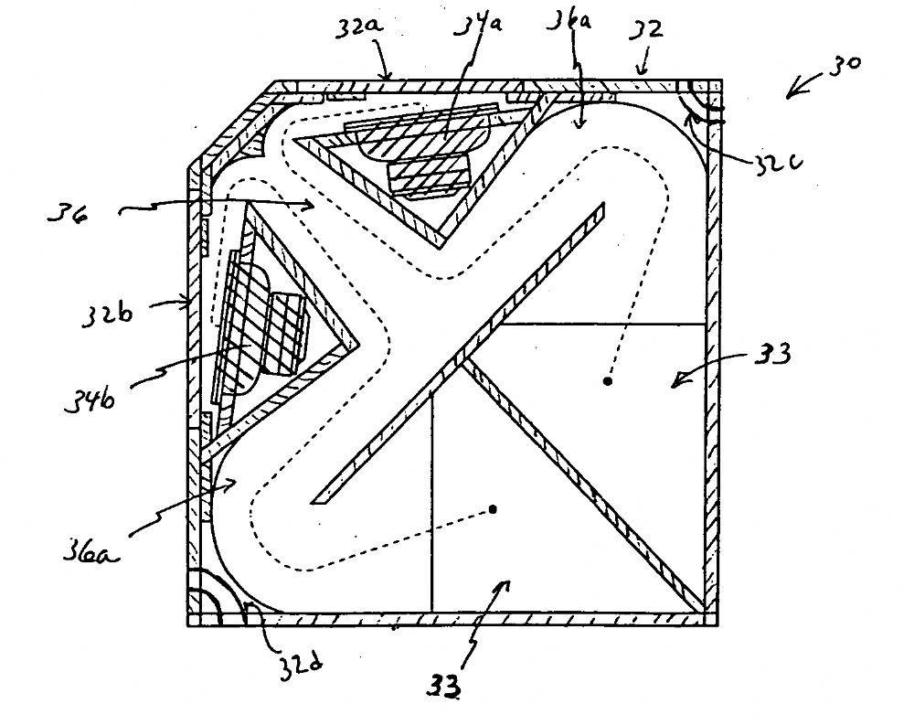
| The original concept was called the BDEAP (boundary dependent external air path) sub. It's a normal horn that doesn't fully expand until after the relatively small opening. The boxes are positioned in a way that then allows the uniform expansion of the horn to continue beyond the opening using the ground and the outside face of the boxes as the boundary. Its a great idea because you end up with the performance of a big horn with half the footprint. |
Posted By: Keen
Date Posted: 28 September 2023 at 10:24am
| I'll help you build one if you like, they're pretty cool. I've been working on a plan lately |
Posted By: SalixSound
Date Posted: 11 December 2023 at 7:44am
| FKA Kapha Sound here. I'm still planning on building a 15in concept around this design. The other notable design that's similar imo is the Lambda Labs digital horn. My main question at this point is how much tolerance there is for a gap between cabinets. For example I've seen as much as an inch or 2 between Danley BC218s which I'd have to imagine would impact the coupling effect to some extent, but those cabinets are monsters and I doubt most folks using them really need a -3 down to 26hz. I did notice that just like the Digital horn the new BC215s include a removable panel that allows you to seal all sides besides the mouth perhaps to reduce any negative effects from less than perfect coupling between cabinets. If anyone has any CNC connects in the Seattle area let me know and I'll certainly report back. |
Posted By: Keen
Date Posted: 25 December 2023 at 12:57am
|
The closer the cross sectional area of the gap would get to the cross sectional area of the relatively small opening in the box, the closer the concept gets to losing its directivity gain. This is because the radiation starts to use both front and back of the box thus radiating in 360 degrees before the ‘horn’ path terminates therefore losing any directivity gain. Small gaps of a few inches between boxes or the ground won’t affect much loss in directivity gain.
|
Posted By: PTSD
Date Posted: 09 August 2024 at 4:43pm
|
Hey this thread is rly old but I am curious if you ever managed to draw up a plan for a subwoofer functioning in this way? If yes I would be interested if you would maybe share some info with me. |
Posted By: Keen
Date Posted: 21 August 2024 at 2:11am
Introduce yourself, tell us about your plans and/or current setup first. 
|
Posted By: PTSD
Date Posted: 27 August 2024 at 3:40pm
|
Ok Sh**t... Wrote a rly long detailed response and reload the page and all is gone... But happy to tell more this time a bit shorter haha Dutch based and I build as a hobby a Soundsystem with my friends/crew. Currently still at a early stage. Tops: JBL HLA 4895 x4 so currently run 2 pairs in stereo but planning to get more potentially in the future. Amps are all Crest CA but also a few Crest pro series (old once). DSP are London soundweb Blu series but also got a Xilica XP4080 and a XTA448 not yet fully decided what to use in the filed but tend towards London soundweb atm. FOH mixer: Midas U16 System mainly used for electronic music anywhere from slow to very fast (BPM in the hundreds) both low and high distortion music. Subwoofer section is atm still fully missing which is why I am asking here because I was very happy when I heard the old bDEAP subwoofer Tom designed before the BC series. The combination of High sensitivity and directivity without the need to use cardiod... Makes me especially intrested into this design besides the fact that I found the sound characteristic the last time I heard them very convincing them being able to play quite high having for my oppinion a nice transient response and "kick/punch" characteristic (ofcause not unique but still). And the distortion characteristics if I remember where also rather nice not being high especially when crossover the subwoofer somewhat higher. So obviously I can't afford due to it being a hobby besides UNI to buy real BC subs and bDEAPs being not available atall in Europe knowing only a single person who owns them personally. So because of that I look for plans simmilar to these designs. I like the fact that the Bdeap used 12 inch drivers with the only negative aspect being that they are not designed to be layed on their sides like the BC215. (Because the JBL HLA are quite big so I need a bit base to place them on) So anyways I hoped that maybe here someone was able to design a subwoofer of simmilar character that he might be willing to share with me because my personal simulation skills in AKABAK... Are still quite limited and I wouldn't know how to model and design subs like these. Hope this answers some of ya questions if not... please feel free to ask. |
Posted By: fudge22
Date Posted: 27 August 2024 at 8:15pm
|
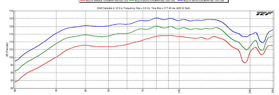
This is from the patent, so in the public domain.
The shelved response is probably why it sounds punchy.
< ="text/">p { line-height: 115%; margin-bottom: 0.25cm; background: transparent } < ="text/">p { line-height: 115%; margin-bottom: 0.25cm; background: transparent } |
Posted By: Contour
Date Posted: 27 August 2024 at 9:18pm
| This BDeap uses drivers which must be very close to the Eminence LAB12 as used for LABhorn, since both were developed same time by Danley. |
Posted By: PTSD
Date Posted: 27 August 2024 at 10:33pm
|
Yea I already considered to just build the Bdeap because of the puplic domain. Just currently don't have the exact internal dimensions because the patent paper only includes the layout and ya can figure out the horn length but exact once might be ofcause best. The only issue with them are that I would need to use for example scaffolding for the tops because the tops are 800mm deep with the Bdeap being quite short in the depth (something like 600mm? Or soemthing like that) So a modified version which would allow to lay them on the side like the bc115 would be ideal but wouldn't know what's the way to design the modification altho I can imagine there prob some not too complex maybe. And yea I guess it's the respondse which also goes white high and the amount of air 4 of these stacked once can push in such an small area.
|
Posted By: PTSD
Date Posted: 27 August 2024 at 10:36pm
|
Are there currebtly alternatives to consider because the lab12 are still available? |
Posted By: asaa00
Date Posted: 28 August 2024 at 12:58am
|
Do you know the total dimensions for the box? I can figure out the internals based on this pic and those measurements ------------- http://soundcloud.com/asaa - My Studio Productions |
Posted By: Meat Substitute
Date Posted: 28 August 2024 at 6:40am
|
I'm not sure this has been cited in this thread but BDEAP clones were done by members more than a decade ago. https://forum.speakerplans.com/terminator-horn_topic25407_page1.html" rel="nofollow - https://forum.speakerplans.com/terminator-horn_topic25407_page1.html
|
Posted By: PTSD
Date Posted: 28 August 2024 at 10:45am
|
Oh haha I never saw that thread normally looked at all of them but yea this one also don't got the messurments but there was one on another forum where they already made a guess but it was too uncertain for me. But I got outside messurments somehwere I think I will take a look atlest i can share them from the tech sheet already the others are maybe on a hard drive I can't access atm
|
Posted By: PTSD
Date Posted: 28 August 2024 at 10:52am
http://www.best4show.com/files/produkte_2_SPL-Bdeap-32.pdf Here is the tech sheet and I just realised I talked totally BS above about the depth... Excuse me. 106x106x46 cm |
Posted By: Contour
Date Posted: 28 August 2024 at 4:39pm
| Just start a cad drawing using those dimensions, and see if you can fit LAB 12 drivers in there, just as shown. If that fits, most other dimensions should also be close to reality. |
Posted By: Keen
Date Posted: 29 August 2024 at 9:36am
|
Perhaps consider the Ciare 12.00SW, B&C 12BG100/12FG100 or the Celestion FTR12-4080DL, Because these designs will allow the use of a much larger chamber than the LAB SUB, the Lab12 driver is not required. Preference would lye with Ciare or Celestion and make use of the available xmax. |
Posted By: Keen
Date Posted: 29 August 2024 at 9:59am
|
build em like this, easier to load, more chamber etc https://imgur.com/a/1fYwVdm" rel="nofollow - https://imgur.com/a/1fYwVdm
|
Posted By: Keen
Date Posted: 29 August 2024 at 10:02am
|
Go 4x12 each box
|
Posted By: PTSD
Date Posted: 29 August 2024 at 10:34am
Ah yea true that you would have a bigger chamber altho ya would also have a smaller horn path right needing to make the speaker a bit larger to compensate ?
|
Posted By: PTSD
Date Posted: 29 August 2024 at 10:48am
Yea I can imagine newer drivers with more power handling can be nice with more xmax. The ciare and xeleston def look not bad but the B&C response I found not very nice actually for this subwoofer application maybe I get it wrong but the 12BG fell off super early. The only thing for me would be that I especially look for sensitivity because I work with the older Crest amps I don't got as much power available as it I would have if using Powersoft& co so I like to find a nice Ballance for that.
|
Posted By: PTSD
Date Posted: 29 August 2024 at 10:52am
Fitting the driver probably not the issue next month when I got my workstation back running I will probably draw up a example. Just with the exact folding of the horn... I am not quite certain. Managing a working horn is probably not a big issue but getting the horn folding optimised I imagine is a bit more tough. But yea I am not very experienced with that haha
|
Posted By: Keen
Date Posted: 31 August 2024 at 11:45am
Yes but the loss of this first fold is much less significant in these external boundary designs because your horn path is extending outside the box. Also consider that the box is already huge and you’ll only need 2. May as well make them 1220x1220x810 in which case the horn path ends up being something like 3m even more I think. It‘s the least of your worries with this approach.
|
Posted By: Keen
Date Posted: 31 August 2024 at 11:58am
I know what you mean with the BG. Do you want to share your input data? You can change that roll off by adjusting the expansion rate of the horn. There’s also some other things worth discussing re how to simulate the inside/outside transition, horn mouth size etc
|
Posted By: Keen
Date Posted: 31 August 2024 at 2:04pm
Sorry only just read this and other posts. Thanks for sharing. Also, didn’t realise you were using Akabak not horn resp. I haven’t used akabak but would be interested to learn. Can help with horn resp though. Re optimising horn path; it’s a moot point. Rather, optimise the response in the simulation software, then build the horn to suit, etc. Cheers
|
Posted By: Keen
Date Posted: 01 September 2024 at 3:13am
|
Actually I have already spent many hours optimising both a 412 and 612 version of these subs and drawn the plans to suit. I draw the plans up by hand on grid graph paper to a variety of scales. The next step is to turn that plan into a virtual plan. I have never done this but perhaps you would be interested. I could email you pictures of my plans. I’m reluctant to put stuff up on here because of those Chinese’s thief’s.
|
Posted By: fudge22
Date Posted: 01 September 2024 at 4:54pm
Based on the patent image, and the manufacturer’s specifications, the “horn” path length is approximately 1.5m. How did you determine that the effective length would be 3m? Can you provide a link or some peer reviewed paper to back up your claim? The box may be huge in relation to a simple bass reflex, but given that the wavelength at 100Hz is 3.4m, in acoustic terms it is quite small. Most of the boundary effect will be due to the ground plane, something that any cabinet placed on the floor will benefit from. At bass frequencies the cabinet provides insignificant loading. |
Posted By: Keen
Date Posted: 01 September 2024 at 10:55pm
As I understand it the main point of this approach is that when two boxes are together with their large side facing forwards (in other words placed on their edge) and the relatively small openings placed together in the centre on the ground, the large outside front face of the combined boxes becomes part of the horn. Therefore it seems appropriate to simulate the arrangement by including this extra section. Effectively the full length from the ground to the top of the box. The effective horn mouth also dramatically increases and imo should be simulated as such. In the case of the patent image it’s 1.5m inside the box then the extra 1m for the external boundary. As I suggested building a design that’s 1220x1220x810 (to make efficient use of ply wood dimensions) which is a bigger physical box than the box in the patent, then horn path in this case would extend beyond the 3m mark. Cheers, and no sorry I don’t have any evidence to back this claim up but it does seem pretty straight forward tbh.
|
Posted By: fudge22
Date Posted: 02 September 2024 at 12:43am
The physical opening in the cabinet is too small for this design to be considered as a horn. For the radiation impedance to be to be nearly resistive the effective circumference needs to be greater than one wavelength of the lowest frequency reproduced. A square mouth can be considered to have a circumference equal to a circle of the same area. It is difficult to achieve this in a practical horn which has to be moved, hence the use of multiple horns. At low frequencies, this is more like a tuned pipe, and the end correction is usually taken as 0.6r, where r is the radius of the pipe. Where the end of the pipe is flanged (as with this design) the end correction goes up to 0.8r At best the the effective length is about 0.25m longer than the physical length. You might also consider reading up on flare rates and cutoff frequencies. If you put a drive unit in the middle of a 2m square board, you wouldn't model it as a horn with length 1m. |
Posted By: Keen
Date Posted: 02 September 2024 at 2:02am
| How are you comparing the opening to a drive unit? |
Posted By: Keen
Date Posted: 02 September 2024 at 5:49am
Sweet technical flex Fudge, but to me it’s a simple horn. The path is expanding inside the box, the cross sectional area of the combined horn paths transitions into the opening which shares the appropriate cross sectional area for that point in the horn to continue expanding through the opening, then the horn continues to expand with the front face of the boxes and the ground until it hits the edge. Complicate it all you like but to me it’s very straight forward. Or bent, as it were ;)
|
Posted By: Keen
Date Posted: 02 September 2024 at 2:21pm
|
I should have been more clear that this is not trying to create the boundary control design rather just use some of the obvious beneficial aspects of the idea. For example I couldn’t ever understand why the cross sectional area of the horn paths inside the box just before the opening were bigger than the cross sectional area of the opening. This is probably some super technical aspect of those designs that I obviously don’t understand, or maybe it’s not and it’s just the way they build them because it doesn’t matter much, who knows… Anyway I became much more interested in designing the layout so the last parts of the horn inside the box both have a cross sectional area equal to that of just under half the size of the opening (which you can see, btw, roborg had also come to that conclusion if you study those pictures). That way it’s all just another fold in the horn. This actually gave space to add more folds inside the box. (As this somewhat contradicts a previous point I was making regarding losing a fold in return for easier driver loading, I should say that I hadn’t realised at the time because I hadn’t looked at the plans for so long but also that my general feeling when working with these ideas was that indeed achieving a suitable horn length is not a problem at all here. Also I was addressing PTSD and I would have got more into those details later on as I did mention briefly. So apologies for somewhat contradicting myself there) More importantly, all of these ideas came together in a perfectly reasonable and simulatable (if that’s a word) way and in a box size that was very friendly to a sheet of ply. I’m confident it would work in this arrangement and the sims are stunning. Perhaps it’s not as technically savvy as some may require it to be to meet their standards but that doesn’t worry me at all. As long as the physical model is translated accurately to the simulation software which as far as I can see, it is, then it’s worth building. Call it the non technical external ground guidance sub. lol |
Posted By: fudge22
Date Posted: 02 September 2024 at 8:00pm
The acoustical impedance at the mouth of the horn is usually assumed to be the same as that of a piston in an infinite baffle.
I would tend towards maybe it's not. However mass loaded quater wavelength pipes are a thing.
In this design, if you consider the the external surface of the cabinet and the ground as parts of the horn, that horn has two sides missing. There is no boundrary to define the crosssectional area as you move away from the opening in the cabinetm so how do you model it? |
Posted By: Contour
Date Posted: 02 September 2024 at 9:15pm
| By stacking two cabinets you add a fictive third wall, effectively each cabinet sees a small room corner section, which has a rapid expansion but can be seen as a horn i suppose. This explains why in the BDeap the last part of the horn expands quickly, to match flare rate. |
Posted By: Keen
Date Posted: 02 September 2024 at 11:05pm
|
Yeah, it’s only got two sides but because it’s big enough the sound travels an extra metre before it knows any difference between that and a rapidly expanding flare rate. I imagine a bubble coming out of the opening and popping when it gets to the edge. |
Posted By: PTSD
Date Posted: 03 September 2024 at 6:11pm
If you like I could maybe try to translate it into a cad drawing and prepare it for AKABAK I am also no expert so at some point would also require some help figuring out how to get it fully correct. But in theory I could model in there also the case for 2 or even 4 subwoofers togather. We could also keep the actual files and drawings by email... If you don't like to have it online untill maybe the plan gets more complete and it makes sense getting more input from the community. Ofcause I would just take first a look to see if it's something I imagine because for me especially scalability is important.
|
Posted By: PTSD
Date Posted: 03 September 2024 at 6:18pm
Would you tho not get a way worse QW step response if it was a quarter wavelength pipe ? Because don't know any quarter wavelength pipe sub that is able to play this high without high distortion but maybe I am confusing some things atm?
|
Posted By: fudge22
Date Posted: 08 September 2024 at 9:29pm
|
Having now read the patent, rather than just viewing an isolated image, it is now more apparent how the external surface increases the length of the horn; although I would dispute the claimed 1m extra. I couldn’t see a reason given for the reduction in area at the exit of the cabinet, so not an ideal horn.  However, I can’t think of any occasion at live events that I have been involved with, where this setup could have been used. There can be very few occasions where this design can be used to it’s full potential.
With regards to the claim in the patent that existing sound equipment does not take account of its physical surroundings, I can’t believe that they are unaware of Mr Paul Klipsch and his 1945 patent. The idea behind this design is not new. Some of the technical information appears to have been lifted from Dinsdale’s series of 1974 Wireless World articles. Other claims are misleading and some information is technically incorrect. Most of the supposed benefits of this design can be obtained with any loudspeaker by placing them against a wall, or in a corner. |