Converting ports
Printed From: Speakerplans.com
Category: Plans
Forum Name: Ported Enclosures
Forum Description: Post all your reflex and bandpass and 'other' boxes with holes in stuff here...
URL: https://forum.speakerplans.com/forum_posts.asp?TID=108202
Printed Date: 26 March 2026 at 6:55pm
Software Version: Web Wiz Forums 12.08 - https://www.webwizforums.com
Topic: Converting ports
Posted By: FOO
Subject: Converting ports
Date Posted: 28 November 2023 at 9:40pm
|
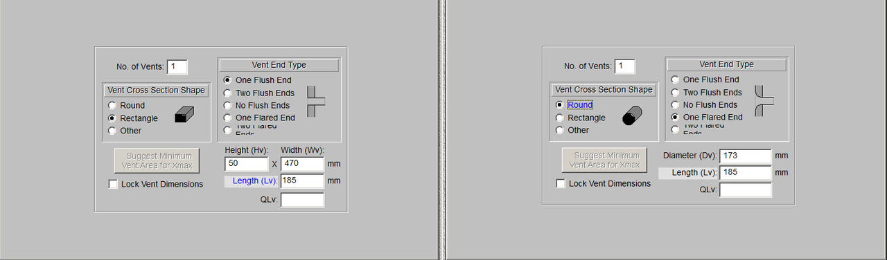
I have a BR design with a slot port without flare, but i need to convert it to a flared oval shaped port. Slot port is 50x470mm and 185mm long. Should give 4,3475 Liters. Am i on the right track if i make a port with the same crosssectional area and length as the slot port? What does the flares do for the total length of the port? The goal is to ad a 25mm radius flare at both ends. What would the total length of the 185mm long port with 2x radius 25mm flares be? From what i understand i have to take the effective length (185mm) and add half of the flare radius (12,5mm) to the effective length of the port. In this case that would be 185mm + 12,5mm + 12,5mm = 210mm. That will end up being a 235mm long port including the 2x radius 25mm flares. Is this total bull? And finally, what would these changes do to the sound and performance? |
Replies:
Posted By: smitske96
Date Posted: 29 November 2023 at 7:01pm
|
If the slotport is adjecent to some cabinet walls, tuning will be lowered because of it. Also I would not put such a radius on the ends. You will need a much larger curved vent with those sizes.
|
Posted By: Elliot Thompson
Date Posted: 29 November 2023 at 7:06pm
There should be no difference. You should just scale the box and let the software simulator predict the performance. Best Regards,
------------- Elliot Thompson |
 FOO wrote:
Posted By: smitske96
Date Posted: 01 December 2023 at 10:51am
|
@Elliot As said before, port placement does matter. As far as i am aware the above program does not take in account any boundaries just like hornresp, winisd etc. |
Posted By: FOO
Date Posted: 01 December 2023 at 6:42pm
| The port sides are up against the side wall. Like on the Gsub. |
Posted By: Elliot Thompson
Date Posted: 01 December 2023 at 7:07pm
Yes. Port placement matters based upon frequency tuning and/or the overall dimension of the box. Since FOO never offered anything other than the port size, it is up in the air what is the dimension of the enclosure. So from a port standpoint, there should be no difference from a rectangular to circular port, all things considered equal. There are old spreadsheets (pre Windows XP days) that will show the influence of the port output. However, such spreadsheets half long faded away due to operating systems moving forward with technology. Best Regards, ------------- Elliot Thompson |
Posted By: FOO
Date Posted: 01 December 2023 at 7:19pm
|
Sorry, but plans only exist on paper for now. But it's a box measuring 950x1000x500mm (DxHxW). Tuning should be 35hz. That's what I have been told.
|
Posted By: Elliot Thompson
Date Posted: 01 December 2023 at 7:43pm
|
Without adding the driver in the equation and, using 18 mm wood, the tuning is 25.29 Hz. So the port only comes into play when frequencies approach 25 Hz and below. Bear in mind that is without any loudspeaker(s) taking up internal space. So the tuning could be higher than that. Possibly, it may be best to build your own box based on your driver's specifications. Best Regards,
------------- Elliot Thompson |
Posted By: FOO
Date Posted: 01 December 2023 at 8:42pm
|
Aaarh sorry you want the internal volume of the chamber? That's 190L. The chamber with the driver is part of a larger enclosure. Just like a Turbosound TMS4. But not hornloaded  |
Posted By: fudge22
Date Posted: 01 December 2023 at 8:52pm
|
If you don’t know the basics of flared port design, how did
you determine that the radius of the flare needed to be 25mm? There are quite a few academic papers on this topic. A good
one to start with is: Maximizing
Performance from Loudspeaker Ports by Salvatti, Button and Devantier It used to be downloadable from jbl’s web site, but I don’t
know if their tech library is still available. A quick internet search, using
your favourite search engine should locate a copy though. This paper references
plenty of other works on the topic, which are worth looking at. Unfortunately, to determine the exact difference between the
cabinet with the flared and unflared ports, you would have to build a couple
and listen to them. If you are just building someone else’s design, it might be
best just to stick with the original port. |
Posted By: Elliot Thompson
Date Posted: 01 December 2023 at 8:52pm
|
FOO. No need for the internal chamber. You are approaching the method backwards (reverse engineering). Just build a box based on your loudspeakers TS Parameters. You will have more control on getting what you want than, trying to make a box work based on it's limitations. Best Regards,
------------- Elliot Thompson |
Posted By: FOO
Date Posted: 01 December 2023 at 9:14pm
|
The flare radius are purely for good looks. I have milling bits from Radius 25mm and smaller, so I just had the idea going with the biggest possible. The box is designed around the driver (18sound 18lw1400). The idea to make a round port with flare instead of a slot is purely for good looks. But sounds like I have to stick with the slot then. This is not a box for the road. It's for my man cave  Raw plywood layered together and coated with a clear varnish
|
Posted By: fudge22
Date Posted: 02 December 2023 at 4:30pm
|
There is nothing wrong with a round port, and if you can get it to fit, it should work OK. There are successful loudspeakers with all manner of shapes, so it is possible to make any shape work. The problem is that ports are inherently nonlinear (unintuitively, a flared port can generate more distortion at high levels than a straight port), and unless you have some knowledge of acoustic design, by which I don’t mean being able to copy the T/S parameters into some software package and click the go button, it is probably best to stick with shapes that have been tried and tested. Round is a tried and tested shape. The tuning of a port, flared or otherwise, is a function of the port cross sectional area to port length ratio. Predictive software simply works out the diameter, or wall lengths, if rectangular, based on the cross-sectional area of the port. You can do this manually for any other shape. The end correction modifies the effective length by some fixed amount and is needed because the radiation impedance of a port is not zero. Finding the end correction for flared ports is difficult, because of the many possibilities to vary the flare amount which changes the inertia of the flow at the port exit. Even if there is a box to tick in the software choosing a flared port it more than likely is just an estimated/guessed amount. One advantage of round ports is that there are a lot of plastic pipes available, and it is relatively cheap and easy to change them out to fine tune the resonant frequency. With a 3D printer it should be equally easy change port designs for any port shape and/or flare amount. On a positive, note while slight variations in tuning might
make response changes look severe in software simulations, in real life you
might not hear much difference. So, if having a rounded end to your port makes
you happy, then go for it. It has been shown that with flared ports the tuning
is mainly dependent on the minimum cross-section rather than the maximum.
Because you are essentially only rounding the end of the port ignoring the
routed round over, and treating it as though it is straight, should get you
close enough as a starting point. |
Posted By: DMorison
Date Posted: 03 December 2023 at 2:44pm
Useful info. Bill Collinson wrote a small app called Flare-It based on real world measurements of flared, circular vents, so start here: https://www.subwoofer-builder.com/flare-testing.htm" rel="nofollow - https://www.subwoofer-builder.com/flare-testing.htm Cheers, David.
|
Posted By: Elliot Thompson
Date Posted: 04 December 2023 at 2:29am
|
FOO
Instead of worrying about the port, you should confirm if the woofer will give you low frequency extension you are aiming for. When port noise is louder than the actual loudspeaker propagating sound, it usually means the user is trying to achieve frequencies in which, the woofer's voice coil cannot produce.
The Eighteen Sound 18 LW 1400 is a PA Woofer. Based on the woofer's (TS Parameters) calculations, 55 Hz (-3dB) is lowest you can achieve before the woofer's voice coil stops producing sound... At least anything that offers some means of significance. The piston will still be active nonetheless using every bit of the xmax trying to make up the loss. However, the sound is determined by the voice coil not, the xmax. This is why, xmax is not accounted for in the TS Parameters calculations.
Best Regards, ------------- Elliot Thompson |
Posted By: fudge22
Date Posted: 04 December 2023 at 8:39pm
|
Can you clarify what you mean by using every bit of the xmax
trying to make up the loss? My understanding is that xmax is a mechanical
constraint and determines the maximum output when it is reached before power
input becomes the limiting factor. Its value is either calculated from the
voice coil and magnet gap length, or set at some point where the measured distortion
rises above a chosen value. Xmax is not part of the TS parameters, because the
latter are small signal parameters. The response calculated from them is the
response at low levels. The voice coil doesn’t stop producing sound below a certain
frequency, it is just that the cone needs to move further at lower frequencies
to achieve a constant output so xmax is more likely to be exceeded at lower
levels. However, with bass reflex cabinets, cone movement is reduced at
resonance, and it is possible that xmax can be exceeded above the tuning
frequency as well as below. For the drive unit in question, according to winisd, in a
190 litre enclosure, tuned to 45Hz, the transfer function gives -3dB at about
40Hz. With 1000W input signal, the xmax limits the output below 38Hz, and then
again between 55Hz and 65Hz. At box resonance (45HZ) the cone amplitude is only
4mm, well below xmax; you need to get above 118Hz before it drops to this level
again. Bass reflex cabinets behave like fourth order high-pass
filters. The reason that the response falls off quickly below the box tuning
frequency is because the output from the port is out of phase with the cone, so
they tend to cancel each other out. Re the webpage linked to: The author provides graphs of port aspect ratio to air
velocity. I couldn’t see anywhere to say how the air velocity was determined.
This is usually measured using a hot air anemometer. Did I miss something?
Also, based on how he specifies the aspect ratio, anything below 1 means that
the exit of the port is smaller than the main section of the port. |
Posted By: Elliot Thompson
Date Posted: 04 December 2023 at 11:23pm
|
You will need to start measuring the dB versus Frequency levels of woofers in free air.
All loudspeakers have a frequency limit in which, the dB level will decrease. You can feed the woofer 20 Hertz. The xmax will move 20 cycles per second however, it does not mean the voice coil is producing anything significant dB wise @ 20 Hertz. The end result is hearing all types of mechanical noises and very minimum sound at 20 Hertz. Then, wondering why the port noise is louder than the speaker once placed in a reflex box at the given frequency.
I've conducted such tests decades ago and invested heavily in a lot of raw speakers that confirmed what Harristech Software predicted. From my experience, Harristech is the only software company that offers such a feature that allows you to determine the -3 dB roll off point of any TS Parameters calculated in it's software.
Remember -3dB is half the output you will get out of the amplifier. So 1000 watts is now 500 watts. The remaining 500 watts is wasted in heat all courtesy of the voice coil in addition to kissing your efficiency goodbye.
Best Regards,
------------- Elliot Thompson |
Posted By: fudge22
Date Posted: 06 December 2023 at 9:08pm
|
While measuring a loudspeaker in free air can be useful to
determine the electro mechanical parameters of a loudspeaker driver, if the
manufacturer has already provided the parameters, I’m not sure of any benefit
in doing so (unless you don’t trust them). I’ve never seen a practical
loudspeaker that has not been mounted on a baffle or in some sort of enclosure.
Given that the enclosure will affect the response, surely it is better to
measure the response of the combined system; especially as the total acoustic
output from a reflex loudspeaker combines both the output from cone and the
port.
I’m not sure whether you don’t understand how xmax works, or
whether you are trying to explain it in a way that I don’t understand. First
you say that xmax tries to make up for the lack of output below the -3dB point
and now you say that xmax moves at 20Hz. It comes across that you believe xmax
is only relevant below the -3dB point on the transfer function, and is used to
compensate for the drop off in response; thus in the bandpass region of the
response it is irrelevant. Xmax is a single value, with the units of mm; it is
the maximum amplitude that the cone can move before the output becomes significantly
nonlinear. The value is either calculated or measured. As stated previously, xmax is not a TS parameter. When
calculating a response, either manually or using software, the TS parameters
don’t consider the signal level. It is a bit like the formula used to calculate
the frequency response of an electrical filter. You can calculate the values of
the components to give the desired response or cut off frequency, but the values
tell you nothing about the voltage and current needed. A graph just shows the
output response, relative to a reference level, with a constant input signal. If you have two identical drive units, except for the value
of xmax, the calculated response for a given enclosure will be identical. In
real life, at low levels, the measured response will be the same, however, the
loudspeaker with the lower xmax will not be able to get as loud. If you take
the 18sound drive unit mentioned in this thread, and limit xmax to 4mm instead
of 9mm, the transfer curve will be identical, however the maximum output obtainable
will be less up until 125Hz. At 65Hz the maximum output will be 7dB down. If you model an Eminence Delta15, the transfer function can
be made flat down to 28Hz, but the maximum output at 50Hz is 15dB down relative
to the output at 150Hz. (The parameters were from the internal database. I
haven’t confirmed whether they are correct). If anyone wishes to confirm this, it is easy enough to do so
in winisd.
Congratulations on your decades of heavy investment and
testing. However, I suspect that you are in a minority if you believe that the
Harristech software is the only software that allows the response, including
-3dB point to be calculated from TS parameters. There are other programs that
can model the response quite accurately.
I’m not sure there is any easy way to tell you this, but the maximum efficiency for an 18” speaker at 40Hz is 4% (see Keele -Max efficiency of direct radiator), so very little efficiency to kiss goodbye. Of the 1000 Watts coming out of your amplifier 960W are wasted as heat in the voice coil. Fortunately, it doesn’t take much acoustic power to get loud. |
Posted By: Elliot Thompson
Date Posted: 07 December 2023 at 4:08am
|
You will need
to start measuring the dB versus Frequency levels of woofers in free
air. While
measuring a loudspeaker in free air can be useful to determine the electro
mechanical parameters of a loudspeaker driver, if the manufacturer has already
provided the parameters, I’m not sure of any benefit in doing so (unless you
don’t trust them). I’ve never seen a practical loudspeaker that has not been
mounted on a baffle or in some sort of enclosure. Given that the enclosure will
affect the response, surely it is better to measure the response of the
combined system; especially as the total acoustic output from a reflex
loudspeaker combines both the output from cone and the port. None of that
can attribute when making a comparison of frequency response vs dB. If the
speaker cannot reproduce a frequency with great efficiency, no amount of xmax
can make up the loss without mechanical noise being the overriding objective.
The benefit of measuring a loudspeaker frequency response in free air is
no frequency restraints due to the size limitation of the
enclosure.
All
loudspeakers have a frequency limit in which, the dB level will decrease. You
can feed the woofer 20 Hertz. The xmax will move 20 cycles per second however,
it does not mean the voice coil is producing anything significant dB wise @ 20
Hertz. The end result is hearing all types of mechanical noises and very
minimum sound at 20 Hertz. Then, wondering why the port noise is louder than
the speaker once placed in a reflex box at the given frequency.
I’m not sure
whether you don’t understand how xmax works, or whether you are trying to
explain it in a way that I don’t understand. First you say that xmax tries to
make up for the lack of output below the -3dB point and now you say that xmax
moves at 20Hz. It comes across that you believe xmax is only relevant below the
-3dB point on the transfer function, and is used to compensate for the drop off
in response; thus in the bandpass region of the response it is irrelevant. Xmax
is a single value, with the units of mm; it is the maximum amplitude that the
cone can move before the output becomes significantly nonlinear. The value is
either calculated or measured. The key word
is tries! However, it cannot produce a frequency in which, the voice coil is
incapable of delivering with great efficiency without adding mechanical noise
in the equation. The confusion may lie as you are looking at a theory whereas,
I am looking at things from a real-world scenario. As stated
previously, xmax is not a TS parameter. When calculating a response, either
manually or using software, the TS parameters don’t consider the signal level.
It is a bit like the formula used to calculate the frequency response of an
electrical filter. You can calculate the values of the components to give the
desired response or cut off frequency, but the values tell you nothing about
the voltage and current needed. A graph just shows the output response,
relative to a reference level, with a constant input signal. If you have
two identical drive units, except for the value of xmax, the calculated
response for a given enclosure will be identical. In real life, at low levels,
the measured response will be the same, however, the loudspeaker with the lower
xmax will not be able to get as loud. If you take the 18sound drive unit
mentioned in this thread, and limit xmax to 4mm instead of 9mm, the transfer
curve will be identical, however the maximum output obtainable will be less up
until 125Hz. At 65Hz the maximum output will be 7dB down. I am not
talking about two identical drivers utilizing identical TS Parameters with
different xmax. I am talking about finding the right driver for the job based
on the TS Parameters. If one wants 30 Hz, it would be better to use a driver
that can achieve 30 Hz flat based on it's TS Parameters and not a driver that is
- 3 dB @ 55 Hertz based on it's TS Parameters.
I've conducted
such tests decades ago and invested heavily in a lot of raw speakers that
confirmed what Harristech Software predicted. From my experience, Harristech is
the only software company that offers such a feature that allows you to
determine the -3 dB roll off point of any TS Parameters calculated in it's
software. Congratulations
on your decades of heavy investment and testing. However, I suspect that you
are in a minority if you believe that the Harristech software is the only
software that allows the response, including -3dB point to be calculated from
TS parameters. There are other programs that can model the response quite
accurately. As I stated,
from my experience. If there is something on the market today that offers such
a feature, I am more that willing to make a comparison to Harristech. However
over two decades ago Harristech was the only one to offer such a feature. The
free programs used by many today does not offer the feature as Harristech I am referring
to.
Remember -3dB
is half the output you will get out of the amplifier. So 1000 watts is now 500
watts. The remaining 500 watts is wasted in heat all courtesy of the voice coil
in addition to kissing your efficiency goodbye.
I’m not sure
there is any easy way to tell you this, but the maximum efficiency for an 18”
speaker at 40Hz is 4% (see Keele -Max efficiency of direct radiator), so very
little efficiency to kiss goodbye. Of the 1000 Watts coming out of your
amplifier 960W are wasted as heat in the voice coil. Fortunately, it doesn’t
take much acoustic power to get loud.
In loudspeaker frequency response measurements, there is a
starting point. That is what many use as reference or a guideline to determine
what is the starting point (insert dB here) to the -3db roll-off point. So, if you
sweep a frequency starting @ 100 Hz (The majority do not cross reflex subs
higher than 100 Hz) downwards, @ 1 watt in which, it is -3dB @ 55 Hz, the
speaker is delivering 0.5 watt @ 55 Hz, despite the speaker delivered 1 watt @
100 Hz.
Best Regards, ------------- Elliot Thompson |
Posted By: fudge22
Date Posted: 07 December 2023 at 9:12pm
|
Thanks for clarifying. |