SyntripP measurement is hot garbage
Printed From: Speakerplans.com
Category: General
Forum Name: Newbie Discussion
Forum Description: Newbie Discussion/Questions. Look less stupid here...
URL: https://forum.speakerplans.com/forum_posts.asp?TID=109111
Printed Date: 27 March 2026 at 4:05am
Software Version: Web Wiz Forums 12.08 - https://www.webwizforums.com
Topic: SyntripP measurement is hot garbage
Posted By: SaladDressing
Subject: SyntripP measurement is hot garbage
Date Posted: 03 June 2025 at 10:13pm
|
Hi! Last year we built pur own syntripps. We already used them quite a bit, but finally got a round to do some outdoor measurements. And what can i say, it looks like hot garbage, nothing like the measurments Art Welter posted. Our SyntripPs consist of 2 B&C 10CL51 8 Ohm and one Celestion Cdx14-3050 each. Some few parts including the phase plugs and throat adapter we 3d printed in petg. Our DSP is a DBX driverack pa2 and our amp a cvr d-654. Sound source is the laptop with open sound meter here is a free field measurment done in opensoundmeter, mid and high driver measured seperately. Mic used is a calibrated minidsp umik-1. https://imgur.com/a/vsnylb6 So we first measured using the dsp settings suggested in the syntripPs thread: https://www.diyaudio.com/community/threads/syntripp-2-way-2-part-virtual-single-point-source-horn.264485/post-4115408 Hot garbage. There is a clear dip at ~750Hz, and recession in the hf. We only got around to try and fix the +750Hz dip, and we tried lots of things. For the measurement above, in the dsp crossover, we put the mid driver lp to 1khz and the hf driver hp to 400hz, and as you can see the dip is still there. It appears the box is not really playing the frequency band at all or very quiet. Ther is no eq applied So we are very much at our limited wisdoms end, and would love to hear some insights from you. if you need any more information, let me know. Would love to hear some insight. Thanks
|
Replies:
Posted By: adamb00m
Date Posted: 04 June 2025 at 5:32am
|
Looks like a time alignment / delay issue possibly. Did you apply the 0.4ms delay mentioned in that link? I’d look at this and also double check polarity is correct. Ideally use smaart to find the true acoustic delay required.
|
Posted By: Jan-2T
Date Posted: 04 June 2025 at 7:32am
|
Did you build the reflex ports or sealed? You can always reverse the HF or MF and input a sine of X-over freq, adjust both channels so they sound the same level then increase MF delay (from zero) untill you get max cancellation. Now un-reverse your signal and the x-over point should be as close as it gets without measuring. Now only phase shift will get some cancellation or summation in the x-over overlapping range. ------------- Music! |
Posted By: SaladDressing
Date Posted: 04 June 2025 at 1:21pm
We first used the 0.4ms, yes. Then we adjusted the delay bit by bit, but it only improved the dip marginally. We triple checked polarity as well. We don't have money for smaart sadly, but why would that delay finder be better than the one opensoundmeter uses?
|
 adamb00m wrote:
Posted By: SaladDressing
Date Posted: 04 June 2025 at 1:24pm
With reflex ports. Interesting, will try next time we measure
|
Posted By: smitske96
Date Posted: 04 June 2025 at 3:59pm
|
Could you post a working link? Can't see the measured response. You have any exact details of the setup? Hight from ground, dustance from DUT etc etc.
|
Posted By: fudge22
Date Posted: 04 June 2025 at 4:41pm
While your comments are valid for setting up and optimising a loudspeaker, if you re-read SaladDressing’s post, you will see he states that the measurements for the two frequency ranges were done separately. If this is correct, any delay or phase reversal between the two ranges will not affect each response. Opensoundmeter has a similar functionality to Smaart, no need for sine waves. The easiest way to set delay times is to measure the high frequency,(or whichever frequency range has the longest path) save the response, and then when measuring the mid frequency, adjust the delay until the phase graphs align at the crossover frequency.
Looking at your measured response, the mid frequency response is not that dissimilar to that of the raw response of the original. Even when simulated, the peak at just below 500Hz, and the sharp drop off at 700Hz is present. That is a function of the design. The deep notch in response at 63Hz could be due to your measurement set up. Try moving the microphone, speaker or both to see if the frequency of notch varies. Also, you could measure the the loudspeaker with a ground plane, which I believe is how the original was measured, it should smooth out the low end response. The funky response of the mid drives, at around 1.6KHz, would normally be of little consequence, because it is out of the operating range and filtered out, either by the cross-over filter or a combination of that and an out of band parametric eq to get rid of any residual leftovers. However, that the high frequency driver shows an almost inverse response over the same frequency range is interesting. As a guess, I would suggest that it is due to some reflection or resonance near to the throat of the horn. If you know how to interpret the phase response plot, that may help. The first thing that I would try is covering the openings for the mid drivers, in the throat of the horn, and re-measuring the high frequency driver, to see if the high frequency response smooths out.
The link works for me. |
Posted By: snowflake
Date Posted: 04 June 2025 at 6:27pm
| when you measured the tweeter did you have the mids either connected to an amp? If not there is not electrical damping. Or you can just short the mid drivers with a wire. Not sure this is the cause but it's easy to try. |
Posted By: SaladDressing
Date Posted: 05 June 2025 at 12:26am
I have a picture of the setup here: https://imgur.com/a/GMOnAbL
|
Posted By: SaladDressing
Date Posted: 05 June 2025 at 12:34am
Hmmm but it's nowhere near as severe in Art's measurements, or am I mistaken? In our measurements it's a ~12db dip, in art's it's only ~6db
Yeah those frequencies I just ignored really, we got some subs taking over from 100Hz down
I actually have the theory that we wired up the hf driver incorrectly. Because there definitely is no inverting happening in the dsp.
Hmmmm, would just closing the mid driver horn ports affect the hf measurement so much?
|
Posted By: SaladDressing
Date Posted: 05 June 2025 at 12:35am
|
Posted By: smitske96
Date Posted: 05 June 2025 at 4:44am
|
I would do a new ground plane measurement. Place the syntripp also on the ground, lets say 4m from mic (if possible) otherwise a bit less would also suffice. Place the mic capsule also as close as possible to the ground and try to get a hard and flat surface. Angle the syntripp in a way that the middle points directly at the mic capsule. That way you get the best actionable data to verify possible problems.
|
Posted By: fudge22
Date Posted: 05 June 2025 at 9:41pm
The response graph in the post that you linked to seems to be post processing. My comments were regarding a comparison with a raw response. Also note that in the Smaart plot the value of the smooth setting is 9. This averages the amplitude at any frequency with adjacent frequencies. To quote the manual, with smooth set to 3, any given data point will represent the value of that point averaged with the next higher and next lower points on the trace. When smoothing is set to 5, each point is averaged with the next two higher and lower points etc. This, as its name suggests, smooths out any sharp changes in response. The below image (from the sameDIY Audio thread) claims to be a raw response. 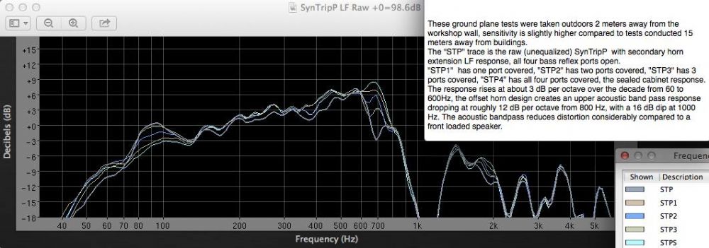 If you eq the response so that it is flat above 200Hz the notch at 700Hz doesn’t look so bad; especially if the measured graph is smoothed.
The anomaly at about 1.6KHz also shows up in this raw response.
When used in isolation, the polarity will have no effect on the frequency response. If the high frequency response was measured with the mids muted, the polarity is irrelevant whether due to wiring or dsp setting. Inverting the signal won’t change a peak in response to a notch. The phase/polarity only becomes relevant when there are multiple sound sources covering the same frequency range. That said, a reflected sound wave also acts as a secondary source, which will combine with the direct wave, either constructively or destructively.
The ports will have some effect, so conversely, eliminating them should too. Just how much, I don’t know. Apart from the coupling between the compression driver and horn, holes in the walls of the horn would seem to be the only other cause. Tracking down problems is a case of eliminating what is not causing the problem. Covering the ports with duct tape is quick and easy, and will either confirm of eliminate the ports as the problem. |
Posted By: FartyMcfly
Date Posted: 17 June 2025 at 4:25pm
|
At the risk of asking a daft question : did you ask Art Welter for advice on diyaudio? For what it's worth, I also got some very weird / crappy results when measuring mine, but it was my first time measuring and well, I got a few food pointers that made me think it was better to start the measurement process again rather than try to analyse or correct my wonky results. |