Tom Danley and Yorkville offer more...
Printed From: Speakerplans.com
Category: General
Forum Name: Advanced Discussion
Forum Description: Advanced discussion area for higher lifeforms
URL: https://forum.speakerplans.com/forum_posts.asp?TID=13807
Printed Date: 19 April 2024 at 11:35pm
Software Version: Web Wiz Forums 12.06 - https://www.webwizforums.com
Topic: Tom Danley and Yorkville offer more...
Posted By: moray james
Subject: Tom Danley and Yorkville offer more...
Date Posted: 12 January 2008 at 1:45pm
|
Check out the new offering from Tom by Yorkville. Of special interest is the use of dual comp. drivers in one inch thick wave guides. Very interesting.
http://vtcproaudio.com/ - http://vtcproaudio.com/ ------------- moray james |
Replies:
Posted By: MarjanM
Date Posted: 12 January 2008 at 5:33pm
|
Veeery interesting! I hope the price wont be too high. ------------- Marjan Milosevic MM-Acoustics www.mm-acoustics.com https://www.facebook.com/pages/MM-Acoustics/608901282527713 |
Posted By: Phil B
Date Posted: 12 January 2008 at 9:03pm
|
I`ve been following this over on PSW for a while...basically taking a few of Danleys current ideas ( Unity and Tapped horns) and adding in the wave guide. Looks good on paper and has some interesting specs.
But prob` never gonna get to hear one in the UK? .p. ------------- Mostly harmless.... except if catering is shut. Solar Sound System Shennanigans.. http://diyhifi.biz/" rel="nofollow - http://diyhifi.biz/ |
Posted By: darkmatter
Date Posted: 13 January 2008 at 10:57am
|
Nice idea, wish I understood the technology better, terrible website though! |
Posted By: Steve_B
Date Posted: 13 January 2008 at 3:40pm
|
I haven't been able to access the site but the title of the PSW thread mentions line array in its title and the original post mentions dual comp drivers and 1” thick, so here goes at a guess how the thing works. Presumably from the above description the device is some form of lens/wave guide that transforms the output of two compression drivers into a line array type exit and that it is 1” thick. Given that the device follows the same acoustic principles as every other device it works by equalising the path length between the comp driver exit and the slot (would be very novel if it wasn't) exit. If the device is patented I would guess that the novelty is in the fact it is 1” deep rather than anything else. Consider a bunch of flexible straws place in front of the comp driver exit. Don't worry about the practicality, just imagine that all the sound goes down the straws. Next arrange the end of the straws away from the comp driver in a line to achieve your line driver. The straws near the centre will bend outwards because the straight line distance from the comp driver exit and the line exit is shorter than the straight line distance to the end straws. The bent path of the straws equalises the path that the sound travels though. This is how most acoustic lenses work. The main difference is how the lens is fabricated. The device Meyer uses in their line arrays works exactly as I have described using 4 pipes. If you search through their patents you should find diagrams that should provide more enlightenment. I experimented with a similar device for a mid range drive unit using garden hose for the tubing. I wrote more details on the Harmony Central line array thread, but the search there doesn't isolate specific posts, so I can't give a link. Back with the comp driver and straws. Remember that they are flexible. If we push the line end of the straws back to the comp driver the straws bend outwards and the overall depth of the device is reduced. I'm not suggesting that Yorkville design uses straws but the concept should give an idea of the principle involved. If we now consider a practical device we will start with a typical 1” comp driver with a diameter of say 150mm (approx 6”). To allow multiple drivers to be stacked to form the array the exit slot need to be at least equal in length to the comp driver diameter. Imagine a pipe shaped like a simple periscope. If this is placed vertically with a length equal to the radius of the comp driver it exits from a point on the circumference and slightly in front of the comp driver. A similar pipe going vertically the opposite direction would define the other end of the slot. Now consider a pipe the same length as the others which travels out horizontally. If at its half way point it is folded back towards the centre of the comp driver the exit can be arranged in the line between the two end exits. By adding additional pipes and adjusting the angles and fold position a complete line can be formed with very little depth. I think I read somewhere on the PSW thread that the path compensation was continuously variable or something similar. It might be that the device consists of a back plate fixed to the comp driver, 1/2” in front there is an elliptical plate whose vertical dimension is equal to the diameter of the comp driver and whose width is equal to the radius and then 1/2” in front of that is a front plate with a vertical slot in it. Obviously there has to be a path around the edge of the centre plate so for the assumed comp driver the device would be vaguely elliptical, 160mm high by 80mm wide and 25mm (1”) deep. Of course I could be completely wrong.  |
Posted By: darkmatter
Date Posted: 13 January 2008 at 4:25pm
couple of screenshots from the website: Steve - completely wrong? I don't think so mate! Cheers for the brilliant explanation! I'll have to have another read sober to properly understand it, tis my birthday today |
Posted By: jethrocker
Date Posted: 13 January 2008 at 4:35pm
|
Hope it's not to naughty pinching these pics so those who can't view the site can have a look... Seems you guessed about right Steve, apart from the fact the CDs are mounted with a larger gap than you expected in the vertical plane..   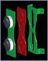 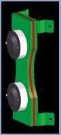 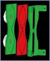  OOps..posted at the same time... |
Posted By: darkmatter
Date Posted: 13 January 2008 at 4:40pm
jethrocker - great minds eh?
|
Posted By: Steve_B
Date Posted: 13 January 2008 at 4:52pm
|
Happy birthday and thanks for posting the pictures. I've just set up a new computer (old one died) and running Linux and Opera I haven't sorted the plug in for flash yet so I get an error when I try to access the site. I think it is bad commercial practice to not offer an alternative but web design is a bit off topic. The vertical spacing of the drive units and slightly longer slot is to keep the spacing equal between different cabinets. The design is a nifty engineering solution if reducing the depth is important but apart from that I can't see any acoustical advantage over the offerings from other manufacturers. |
Posted By: Steve_B
Date Posted: 13 January 2008 at 5:00pm
| Looking at the picture of the back of the cabinet it reminds me of the mid/high horn that Centauri designed. It would be interesting to know what the crossover frequency is and Centauri's comments on getting the bass drivers to operate up to the crossover frequency. I know he did a bit of fiddling with phase plugs and the original Unity horn used a lot smaller mid drive unit. |
Posted By: Centauri
Date Posted: 14 January 2008 at 12:50am
|
It is very interesting. I don't think this is any sort of waveguide though - as soon as you start deflecting/bending the wave around, you will get a massive reduction in high frequency response. The only way I can see this setup working is if the red section in the diagrams is some sort of shaped lightweight diaphram which is being driven from the compression driver output, and re-radiating the sound in an elongated wavefront due to its shape - not the sort of thing that would be DIYable very easily. I wouldn't imagine that the crossover frequency would be very high, but then again, the synergy/unity horns are strange beasts. Anyone here going to buy one to pull it apart and report on the workings ???? |
Posted By: darkmatter
Date Posted: 14 January 2008 at 9:47am
This was the bit that was confusing me - sounds very probable  |
 Centauri wrote:
Posted By: _djk_
Date Posted: 14 January 2008 at 10:19am
|
" I don't think this is any sort of waveguide though - as soon as you start deflecting/bending the wave around, you will get a massive reduction in high frequency response. "
Ever seen the phase plug of an EV DH3?
For that matter, ever seen the phase plug of the BMS driver used in this system?
They're both long, and go through a couple of 90° bends.
The key is the size of things relative to the wavelengths involved, and that looks correct.
If they didn't work great, I doubt anyone would pay Tom for the use of it and create a new company just for this (sure to be expensive) product. ------------- djk |
Posted By: Tony Wilkes
Date Posted: 14 January 2008 at 10:20am
|
The drivers look like standard BMS Neo's. I cannot work out the waveguide at all!! Tony |
Posted By: Steve_B
Date Posted: 14 January 2008 at 12:04pm
|
I think Earl Gedes used a system where he acoustically coupled one diaphragm to another. He called it an acoustic lever. In this system I think it would create more problems than it would get round. If the red section were some sort of diaphragm it would have different resonant modes which would cause response irregularities; at higher frequencies it is several wavelengths long. Cone resonance is what causes the uneven response at the upper range of conventional drive units. If the diaphragm were stiff enough why not mechanically couple it to the voice coil. Also if acoustic perfection were the goal, why worry about making it compatible with conventional compression drivers? Call me cynical, but I would tend to go with the simple approach. It is based on proven acoustic principles, is sufficiently novel in design to get a patent and could be incorporated directly into a compression driver phase plug opening more licensing possibilities. |
Posted By: _djk_
Date Posted: 15 January 2008 at 3:45pm
|
" Gedes used a system where he acoustically coupled one diaphragm to another"
Strictly for a subwoofer. ------------- djk |
Posted By: ArthurG
Date Posted: 20 January 2008 at 5:09am
another nice new concept from Tom. This guy never stops  but one thing hurts me is the use of the BMS drivers. First I hope the xover point is higher than 1,6k since they sound awful below even if the specs say otherwise... and secondly I don't understand why they are so popular (many German brands use and L-Acoustic too). IMHO, they have a lot of distortion and sound clinical/harsh at high volume... really, I don't understand their success... |
Posted By: staiper
Date Posted: 20 January 2008 at 11:30am
|
I believe that "thing" is simple.. (simpler than-we-want-to-be) That is just double parabolic line splinter which equates distances from HF driver throat to vertical slot plane... (ofcourse cleverly dimensioned in respect to wavelengths in "game") + some grade of expansion.
.. I may be wrong .. but that is my opinion
|
Posted By: _djk_
Date Posted: 20 January 2008 at 6:18pm
|
"but one thing hurts me is the use of the BMS drivers. First I hope the xover point is higher than 1,6k since they sound awful below even if the specs say otherwise... and secondly I don't understand why they are so popular (many German brands use and L-Acoustic too). IMHO, they have a lot of distortion and sound clinical/harsh at high volume... really, I don't understand their success..."
I suppose one could substitute another brand of 1" driver.
But how does the BMS sound with only 18.75W?
Because of the difference in efficiency the BMS drivers only need handle 18.75W each (in the crossover region) to keep up with 1200W input to the pair of 10s. ------------- djk |
Posted By: MarjanM
Date Posted: 21 January 2008 at 11:52am
|
I cant imagine the crossover point to be higher than 1KHz. If you look at the spec for some of the 1inch BMS drivers they handle 80W from 800Hz up.
------------- Marjan Milosevic MM-Acoustics www.mm-acoustics.com https://www.facebook.com/pages/MM-Acoustics/608901282527713 |
Posted By: gazman
Date Posted: 21 January 2008 at 8:02pm
| Arthur you've mentioned distortion in BMS drivers before, is that based on measurements you've taken vs other similarly priced drivers (eg. B&C) or listening tests? I just find it hard to believe that Danley of all people would use a HF driver that let down the rest of the system, he uses BMS in the SH-50's as well... |
Posted By: Calitri
Date Posted: 22 January 2008 at 6:28am
|
We had a previous conversation about the BMS drivers so you might want to look back a bit on the general forum, that was about the coaxial driver 4590. But in a general consensus, it seems to divide people into two, others who like and others who don't. Personally I do like them, especially their higher priced neodym range. The basic ferrite models like the 4538/48, can't remember which one, which is in the HK Audio LP115 series and simular newer ones, is a bit harsh'ish as it's crossed so low but it's not bad, it just has a bit of downward tweaking to do in the 1-2.5 kHz range but other than that is pretty good driver considering the price. The reason might be that their harmonic distortion is higher than many other manufacturers' so people might think them as a bad drivers but their manufacturing quality is superb and they can take incredible amount of power and not give out relative distortion or square wave which is the one what I'm more interested about. If you compare lets say a cheap manufacturers drivers and the BMS, then the cheap ones might have less HD in them but when pump more power to them, they start to push out square wave even though you might not exceed the RMS rating as compared to BMS where you can push them easily past the RMS rating without getting any square wave or actual/relative distortion. So, summa summarum, they basically sound the same pushed with low or high power. Tony A.S.S has knowledge about their manufacturing quality and commented about them. Make a search for it in general forum about if you're more interested. |
Posted By: ArthurG
Date Posted: 22 January 2008 at 10:29am
well it seems that you never had experienced a BMS 1" crossed at 800Hz as it sounds completely un-natural and harsh...  |
Posted By: ArthurG
Date Posted: 22 January 2008 at 10:51am
FYI, I have a 50Hz 4PI anechoic chamber with calibrated Earthworks and Clio mics, Audio Precision ATS-2, Clio8 FW QC, EASE 4.2 with Aura module and Easera in my lab. I've made distortion measurement with more than 100 HF drivers from European & Chinese manufacturers during the last 2 years, so my claim is based on facts. Now, I never said BMS is a bad brand. I only said that I'm surprised that many manufacturers use them despite the high distortion numbers. Personally, I don't like them, it's my taste but I can understand that others don't agree. But when you listen side by side BEYMA CP380M ad BMS 4550, it's hard for me to imagine that you can chose the BMS. The Beyma sounds so more natural, with lot of presence compare to the dry, analytical BMS and the Beyma still shows significantly lower distortion numbers... To give you an example, with same horn (90x60 elliptical 210x210x120mm), with 1W/1m, distortion at 2,5kHz (where the human hear is very sensitive): H2 on BMS 4550: 3,98% H3 on BMS 4550: 0,25% H2 on Beyma CP380M: 0,63% H3 on Beyma CP380M: 0,05% with 10 and 30W the ratio is nearly the same... --Arthur |
Posted By: gazman
Date Posted: 22 January 2008 at 8:27pm
|
Cheers for the reply Arthur, some interesting stuff. Quite curious about these drivers indeed, btw have you measured a DE250 against these on same horn at all? Would be interested in figures on that as I like the sound a lot. The website figures (albeit on two completely different horns though) have the Beyma CP380M with 2nd HD about 45dB down from fundamental and the BMS graph shows the 4550 with 2nd HD about 32dB down.Interestingly the coaxial 4594ND, 4595ND and 4592ND all have 2nd HD barely 22dB down from fundamental near the high end (6k up). Only thing I'd heard about those was comments claiming distortion was too bad to drive them down to their recommended 400-500hz but the distortion levels seem to get lower (around 40dB down) as far as 600hz.
|
Posted By: Calitri
Date Posted: 23 January 2008 at 6:10am
|
What is interesting about the coaxial design is that B&C also is doing a version of their own, so perhaps the idea is not as bad as I/you might think. Well, if you look at the B&C version's distortion, heh, now that's a high distortion figure! Like I said in my previous post, I've only done measurements in practical situations, so there's always something else that might cause the feeling of a good sounding unit. Perhaps it's because in large format systems you need quite clinical drivers so that they have enough throw and the sound gets better with a little bit more distance to the speaker. This is just what I've experienced when doing concerts outside. When I heard the F1 Res4 + F218 set in small inside space, they did sound a bit harsh but clean and crystal clear, just as the line array using the BMS top end. But go outside when there's more that 5m distance to the closest speaker and it really starts to sound good. So that's why I don't always look at the HD figures because they're close range measurements, not from a distance and they don't always tell the truth in real situations. But like I said, that's just what I've experienced, so here's my 2 cents! |
Posted By: moray james
Date Posted: 23 January 2008 at 5:28pm
|
Calitri: you said "What is interesting about the coaxial design is that B&C also is doing a version of their own" Do you have a link or url to this information? I took a fast look at B&C but did not see anything. Thanks.
------------- moray james |
Posted By: Calitri
Date Posted: 24 January 2008 at 6:08am
|
It's right under the HF drivers, the DCX50, it's a new design, I believe someone else put the link here also... Anyways, here's the link. http://www.bcspeakers.com/index.php?sez=1&categoria=4&id_descrizione=46&prodotto=199&id_descrizione_prod=54 |
Posted By: bassmish
Date Posted: 24 January 2008 at 11:20pm
|
Hello, I'm not entirely sure what the problem that was intended to be solved by this design was, which makes this a bit pointless, and I'm also not sure if this is what steve B was saying. But. I think what's happening from looking at the picture is that the sound is no longer sent through a horn to present an acoustic impedance, but rather sent around a symmetrical (about the horiziontal) object/waveguide. This waveguide will have dimensions so as to suite the frequencies being transmitted as steve said (smaller than the wavelength?), e.g to eliminate standing waves, not to decrease HF response. The sound passes around the symmetrical object, then is presented with a large acoustic impedance in the form of a 1'' slit/hole. It is forced out of this slit and spreads out, at which point the horns take over combining the two sources in a clever way. Is this what you were saying/obvious? Bassmish |
Posted By: H..
Date Posted: 26 January 2008 at 9:20am
| Slot tweeter on a horn then! |
Posted By: boab
Date Posted: 26 January 2008 at 12:22pm
|
I think that the key may be in the statement... "The Paraline element is a horn configuration that provides an effective impedance transformation while at the same time providing a way to adjust the path length in a continuously variable way, such that the high frequency dispersion pattern produced has the same characteristics as that of a much deeper horn." http://vtcproaudio.com/ |
Posted By: bassmish
Date Posted: 27 January 2008 at 7:47pm
|
maybe, the c'haracteristics of a deeper horn' are just refering to the way sound becomes more omni directional as the frequency decreases, but using this slit and a lot of pressure created by the dimensions of the waveguide, the sound will perform as a 'deeper horn' and spread out a large amount more? Sounds quite wrong. I guess that a non variable path length would just be like a straight tube, so maybe adding a few 90 degree corners creates lots of disturbance in the path taken by the wave and consequently creates a continuously varying path length. maybe this unstability in the path taken by the wave causes a higher pressure inside the wave guide, hence they said, 'such that the high frequency......' |
Posted By: _djk_
Date Posted: 27 January 2008 at 11:32pm
|
"the c'haracteristics of a deeper horn' are just refering to the way sound becomes more "
No, it means the the length of the horn using the same driver would have to be much longer with a conventional throat construction. ------------- djk |
Posted By: bassmish
Date Posted: 28 January 2008 at 1:07pm
|
thats not what I'm on about , just gaining the same performance of a conventional throat horn from a smaller design is not all that this thing does apparently. I was refering to a similar effect of the spreading out/diffraction displayed by light as it passes through a slit, or water through a hose pipe when you squeeze the end. And, a conventional throat horn would not have a variable path length, or would it, what is the meaning of a continuously variable path length? |
Posted By: Calitri
Date Posted: 29 January 2008 at 10:39am
| Just yesterday had an idea about the "deeper horn" part, could it refer to the fact where in normal line array horns the waves from the center of the horn would have to pass the same distance as the sides to create a vertical plane of sound, which is usually done by bending the center path. So perhaps the horn's throat refers to that difference. So instead of say 20 cm long line array horn you can have 2-4 cm long "horn" that creates the same kind of vertical plane, which in my mind brings the question that could it be just a simple Fresnel lens type thingy? It does exactly that type of result but with light so it just might be the same idea adapted to sound... |
Posted By: bassmish
Date Posted: 29 January 2008 at 9:37pm
| I'm doing an experiment on fresnel diffraction at a slit next week for my course, sounds relevant, best have a look at that! |
Posted By: _djk_
Date Posted: 07 February 2008 at 8:23am
From someone that has actually heard them:Got to hear some brand spanking new speakers last week... http://forums.klipsch.com/forums/AddPost.aspx?ReplyToPostID=1014768&Quote=False - Reply http://forums.klipsch.com/forums/t/100572.aspx# - Favorites http://forums.klipsch.com/forums/t/100572.aspx# - Contact
------------- djk |
Posted By: AshayinFLA
Date Posted: 22 August 2008 at 9:22am
|
A company I work with has 12 of these cabinets, and 8 of the double-12" subs. So far, I have not heard them out in the field, but we did listen to a few of them in the shop. They definitely need some eq (apart from the processor settings initially on them). For the most part they come WAYYY too bright. Cutting between 4-8db (depending on taste, etc) from 6.8k> smoothes them right out. They are also slightly harsh in the mids, but a couple of db down at 600-800hz fixes them right up! Apart from that, these are GREAT SOUNDING boxes! They do throw VERY FAR (we walked out of the warehouse and a good 50-75 feet with lots of pressure of in-your-face clean sound!) Theres a few downgrades to using them in the field (at this time you cannot groundstack and point the bottom cabinets at a downward angle, without "figuring out" how to), and the finish is kinda "cheesy" and looks like it will easily scuff or even break! The double-12" subs are SIMPLY AMAZING (well, for 12" subs anyway). The amount of pressure that comes out of these cabinets is nuts! Groundstacked subs made a huge difference over flying 2 subs with the fullrange cabs underneath. My boss is a distributor for these boxes, and although I don't know the numbers, they are supposedly really cheap, in comparison to other similar cabinets! They are priced low because of some of the "weaknesses" like the painted wood, and a few other very little complaints. These boxes are currently in Boca Raton, FL if anybody wants to demo them. Saturday we will be using 1 sub and 2 tops per side as sidefills for kc and the sunshine band. If anybody is interesting I can let you know how their engineer likes them. ps Their processor (4-in, 8-out) is SIMPLY AMAZING for the price! Each output has 8 parametrics + low/high pass filters on each output, as well as up 50 650ms delay (in .01ms steps), full limiter, phase, and a matrix mixer to send any input to each output at whatever level you want. Each INPUT has phase, gain, delay, 8 parametrix, lp/hp, compressor, AND a 31 band graphic EQ (you can use all the eq's at once, not just parametric or just graphic)!!! Every port (input, output) can be named. Theres 30 presets to store your settings! The system has usb, serial, AND ethernet connections to the computer program, but ALL functions can be accessed from the front panel! Also, it is 1 rack space! VTC gets these from another manufacturer (whose name I forget) but they sell CHEAP (well under $1000 for all this!) I think the manufacturer has other units, with up to 8 in, 16 out if I remember right!!!! ------------- -- Adam www.myspace.com/soundmanadam |
Posted By: Steve_B
Date Posted: 22 August 2008 at 1:51pm
|
Without delving in to the theory too deeply, the dispersion angle of a straight sided horn is set by the angle between the two walls. With a given mouth and throat size, set by drive unit choice and operating frequency range, the only way to reduce the angle between the horn walls, and hence dispersion angle, is to make the horn longer. The idea of the various high frequency devices used in line arrays is to create a shallow device that behaves as though it was a long horn. If you don't mind a very deep cabinet, the long horn method should work |
Posted By: turbodeas
Date Posted: 23 August 2008 at 12:35am
|
Interesting stuff. Possibly a bit of a basic question, but the two "holes" across each 10 inch driver - are they there to act as an acoustic low pass filter? I've noticed quite a few line array boxes have their mid drivers partially covered up by some solid material and was wondering why this is, as opposed to just a standard metal grille....I did wonder whether it was to move the point of radiation closer to the HF in order to give more coherancy when the wavefronts combine? Cheers, Chris. ------------- http://www.hotmastering.com" rel="nofollow - http://www.hotmastering.com |
Posted By: Centauri
Date Posted: 23 August 2008 at 1:05am
That is usually the main reason - the higher the crossover frequency, the closer the two sources would need to be. There is also the problem of not having too many irregularities to the horn as far as the HF is concerned - a large hole in the side of the horn will degrade the HF significantly and cause large reflections. Note the vertical slots in the Vertecs. In some experiments I was doing, I brought the high mid throats out to vertical slots either side of the HF (similar to the Worx boxes) and found that covering these with a fine flat steel mesh improved the HF output. |
Posted By: turbodeas
Date Posted: 23 August 2008 at 3:08am
|
Ah cheers, that clears some stuff up for me. So there's no problem with only one side of the mid driver being exposed/loaded? I was just always of the mind that the throat of a horn should come from the centre of the driver, in order to keep pressure across the cone equal - looking at the Danley boxes the mid throats are quite clearly at the edge of the cones..... Chris. ------------- http://www.hotmastering.com" rel="nofollow - http://www.hotmastering.com |
Posted By: AshayinFLA
Date Posted: 23 August 2008 at 3:14am
|
I would think it would have an effect on the lf frequnecy response, but the main reason for that is actually to keep the "sources" of sound less than 1/2 a wavelength from each other. If the sound eminates from more than 1/2 a wavelength away (at the highest frequency the transducer is set to reproduce, since that is the smallest wavelength) then you can get phase cancellations and uneven frequency response across the listening area. That is why so many line arrays use small mid drivers (4-6") rather than larger (10-12") drivers which can reproduce the frequencies just as well. The larger drivers when set next to each other will be too far apart for the frequencies they produce, to keep even coverage at the edges of the coverage area (of course it is hard to hear the difference with music, especially while standing in one point, but if you play pink noise and walk around, the difference is very obvious very quickly, as you will hear the "shape" of the noise changing as you walk!). If you use larger drivers, you can make them "vent" out close together, so the sources of sound are close enough, you eliminate that problem!
------------- -- Adam www.myspace.com/soundmanadam |
Posted By: turbodeas
Date Posted: 23 August 2008 at 6:49pm
|
Riiiiight. I'm well aware of the effects 1/2 wavelength coupling has on sound, I was just unsure of the effects covering half of the driver with wood/metal would have on the sound! Thanks for clearing that up, it's appreciated :] Chris. ------------- http://www.hotmastering.com" rel="nofollow - http://www.hotmastering.com |
Posted By: _djk_
Date Posted: 23 August 2008 at 10:24pm
|
"I was just unsure of the effects covering half of the driver with wood/metal would have on the sound!"
You mean like a compression driver where 90% of the diaphragm area is covered by the phase plug? ------------- djk |
Posted By: turbodeas
Date Posted: 24 August 2008 at 3:42am
|
That did occur to me, but phase plugs are almost always centered on the
diaphragm, thus providing equal pressure across the vibrating surface. I was concerned that the throats on cone transducers in line array systems are often off centre, surely creating an area of much higher pressure at the edge of the cone. Does this not mean a) that breakup can happen easier or b) that the radiated sound from one edge of the cone has to travel further to the throat than on the other? I might be completely wrong here, just trying to clear it up in my head but can't find much conclusive evidence either way! Cheers, Chris. ------------- http://www.hotmastering.com" rel="nofollow - http://www.hotmastering.com |
Posted By: haymere
Date Posted: 24 August 2008 at 8:45am
|
Going back a bit I would just love to try some of danley/yorkvilles unity series
mark
|
Posted By: audiodesignguide
Date Posted: 10 March 2009 at 6:44am
|
ArthurG, what do you suggest about a good 15" to use with CP380M ?
http://www.audiodesignguide.com/HiEff/WooferCompare.html - http://www.audiodesignguide.com/HiEff/WooferCompare.html
------------- Andrea Ciuffoli www.audiodesignguide.com |
Posted By: mykey
Date Posted: 10 March 2009 at 12:15pm
|
my take on it
?
http://img10.imageshack.us/my.php?image=10232067.jpg - http://img17.imageshack.us/my.php?image=26863160.jpg">  ------------- ......just all them hanging there like giant bananas. |
Posted By: Tony Wilkes
Date Posted: 10 March 2009 at 1:21pm
|
Mykey, That's it exactly but it is oval in plan to give you the slot form output. It makes sure that all points on the slot have the same signal path length from the original source. Its just a more compact way of doing what BMS do with their L.A. HF driver. Tony |
Posted By: jsg mashed
Date Posted: 14 March 2009 at 5:44pm
Looks right to me. You've shown the path area increasing gradually as per a horn and this is right I think. But in the top part, the area is expanding as the wave goes out radially, so instead of imposing an exponental profile, you'd want to impose the correction to get from conical to exponential.
The bottom part is more complex, but similar issues apply. ------------- ...because Good is Dumb. |
Posted By: CoblosBrengose
Date Posted: 18 March 2010 at 2:19am
the danley paraline patent is now available for viewing through google. http://www.google.com/patents/about?id=nU3LAAAAEBAJ - http://www.google.com/patents/about?id=nU3LAAAAEBAJ I haven't fully comprehend what's the correlation of Fig. 2 and Fig. 3 related to Fig 4/5/6.  by examining the patent, there are modification in VTC implemention, on the red plywood sheet pictured below in yellow circle: (1) adding cones in front of bms throat, and (2) trapezoids on exit slot.  I think it's DIY doable. |