HD15 Hornresp modellling
Printed From: Speakerplans.com
Category: Plans
Forum Name: HD 15 horn
Forum Description: Discussion / Questions about the HD 15 horn
URL: https://forum.speakerplans.com/forum_posts.asp?TID=1995
Printed Date: 27 March 2026 at 8:37am
Software Version: Web Wiz Forums 12.08 - https://www.webwizforums.com
Topic: HD15 Hornresp modellling
Posted By: ceharden
Subject: HD15 Hornresp modellling
Date Posted: 06 June 2005 at 8:05pm
|
Hopefully a quick question for someone please: I'm trying to model the HD15 in Hornresp to tweak the size of the box, I want to make it the same size as some 18" reflex boxes I use for ease of stacking. The problem I have is deciding what type of horn flare to model it as. It looks much more rapid than most horn flares, even taking into account all the flare is on one side. I'm guessing someone else has done this already, so if you could let me know what parameters you used please I'd be grateful. Thanks. |
Replies:
Posted By: Timber_MG
Date Posted: 07 June 2005 at 2:50am
| Don't forget to add the large front chamber and a little extra length for end-factor correction. Tb_mike posted a link to an article (audioroundtable high-eficiency methinks) dissecting the original Turbosound analytically which said basically 70Hz loading, though practice tells one that in larger stacks(8-12) (you should really use at a very least 4 when expecting any much bass) you can expect something to about 50ish. |
Posted By: ceharden
Date Posted: 07 June 2005 at 6:14am
|
As I can't work out how to model the flare as a single curve, I've been
trying to use multiple conical segments as that's how I'll probably
construct it. Sticking with the original measurements for now I'm
getting CIR > 1 warnings for my final flare segment because of the
speed of expansion. Will this actually affect my simulation
results significantly? I think I've got all the dimensions right (Including large throat and rear chambers) but the results don't quite seem right, eg the diaphragm displacement is quite large even within the horn passband (2mm @ 150Hz, 1W input). If anyone has modelled the HD15 in Hornresp and can do a screenshot of the input params please it would save me a lot of frustration. Thanks in advance. |
Posted By: fernand
Date Posted: 08 June 2005 at 9:44am
|
I have the same question. It might be a good idea to open a thread in the general forum that is reserved for box models. It appears to me that a lot of people try to model the boxes of the plans to see whatever result they could have with a specific speaker. That way, we could avoid to do the same things again and again. Anyone has available model parameters (hornresp, winisd, ...) |
Posted By: tb_mike
Date Posted: 10 June 2005 at 12:34am
|
Post us your input screenshot and wel see whats wrong. I modeled an exponential approximation of it,and it looked similar to the HD15Plot. Ensure driver parameters are inputted in the right order,ensure cubic centimetres or litres inputted..etc Note that on finite horns the loading differences arent so apparent. With one box in 2pi space the excursion can still be high,the horn is too small to support the long wavelengths. Try modeling an infinite hornor HYPEX horn and compare the acoustic impedence and excursion plot etc to realistic horns. |
 As I can't work out how to model the flare as a single curve
Posted By: ceharden
Date Posted: 11 June 2005 at 6:44am
Here is my attempt at the HD15 simulation params. Response
doesn't quite match Rog's on the HD15 page but it seems sensible.  If you could tell me if I'm going along the right lines please. As you say, the flare type doesn't make a great deal of difference. The only other bit I'm not sure about is the throat chamber i.e. what to choose for the area given the throat is not on the same axis as the driver. Cheers... |
Posted By: Dave Slater
Date Posted: 06 August 2005 at 5:57am
|
the axis of the throat doesn't matter it's just the smallest area the air has to travel through in the case of the HD15 the throat area is 544.8cm^2 the front chamber is any space between this and the driver including the volume of air contained within the cone itself on the HD15 the easiest way to figure this out is to use pythagoras' theorum to work out the area of the triangle ie. you know the size of the baffle 42cm and the distance away from the back panel at the top of it is 20cm assuming a right angled triangle the sq root of 42^2 - 20^2 gives 36.9cm or the height up the back panel 20*36.9=738 divide that by 2 and you have the area of that triangle or 369cm^2 multiply that by 47.2 and you have 17416.8cm^3 or 17.4 litres add on 2.5l for the volume of the cone and a rough guess of 20litres for the front chamber would be about right |
Posted By: Timber_MG
Date Posted: 12 August 2005 at 2:24am
| That sim also comes fairly close at the low end to the measured response. |
Posted By: ceharden
Date Posted: 12 August 2005 at 12:45pm
Cheers, good to know I managed to get the sim somewhere near right. Been playing with some variations on the original HD15, slightly deeper cabinet for a longer path etc. |
Posted By: Jimbo
Date Posted: 12 August 2005 at 1:19pm
|
I may be wrong, (and if I am, Please tell me so!) but shouldn't that plot be made at 2 x pi? (1 on the floor?) If I'm wrong about this, I've been modeling a new design all wrong. Jim |
Posted By: ceharden
Date Posted: 12 August 2005 at 1:44pm
|
I'm not exactly sure, but I think 1xpi is appropriate if you use
multiple cabinets together (one HD15 wouldn't be very useful).
For modelling most situations you are right about using 2xpi. Anyone else care to correct? |
Posted By: Jimbo
Date Posted: 12 August 2005 at 3:46pm
|
I just checked the plan and it's listed as quarter space as well. The comment about Rog's plot not matching is more what spurred the question, but any other comments would still be appriciated. Thanks Jim |
Posted By: Timber_MG
Date Posted: 12 August 2005 at 5:00pm
|
A stack of four on the ground would be modelled as a single cab in 1/8th space. Have a go at a different driver perhaps? |
Posted By: Dave Slater
Date Posted: 12 September 2005 at 5:28pm
|
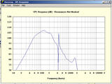
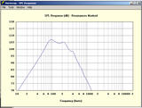
been busying myself with this tonight - bored the missus is out! anyways i figured that the HD215's that Dom and I built have a close enough approximation to the curve using straight sides to allow an approximation of an exponential horn using conical segments i dug out the cad drawings i made and with a bit of working out came up with this :- http://img111.imagevenue.com/img.php?loc=loc21&image=444_HD15_input.jpg"> http://img45.imagevenue.com/img.php?loc=loc295&image=089_HD15_response.jpg"> @ ceharden i made the ATC the same area as the baffle so the axis is normal to the driver. rotated the other way normal to the throat (and therefore a smaller area) caused no end of spurious crap and a complete loss of the bottom end overall compared to the Rogs plot i think its a passable sim hope that helps |

Posted By: Dave Slater
Date Posted: 12 September 2005 at 8:41pm
|
thought it would be interesting to compare so assuming that sim is right here's some more drivers:- PD154 http://img21.imagevenue.com/img.php?loc=loc172&image=4ec_HD15_PD154.jpg"> PD158 http://img44.imagevenue.com/img.php?loc=loc273&image=bdc_HD15_PD158.jpg"> PD1550 http://img111.imagevenue.com/img.php?loc=loc119&image=ef9_HD15_PD1550.jpg"> P.Audio SD-15 http://img46.imagevenue.com/img.php?loc=loc231&image=082_HD15_PAUDIO_SD_15.jpg"> P.Audio P-15N http://img101.imagevenue.com/img.php?loc=loc1&image=d7f_HD15_PAUDIO_P_15N.jpg"> P.Audio SN-15B http://img14.imagevenue.com/img.php?loc=loc88&image=6ba_HD15_PAUDIO_SN_15B.jpg"> P.Audio C15-500LF http://img46.imagevenue.com/img.php?loc=loc275&image=1c6_HD15_PAUDIO_C15_500LF.jpg"> this last one is Rogs fave and clearly it works really well yet the one above it seems to have a reasonable response and that's a Neo driver i'm just wondering what tweaks are nessesary to get them singing properly
|


Posted By: Dave Slater
Date Posted: 12 September 2005 at 8:49pm
|
Norty was asking about the Beyma 15LX60 a while back http://img111.imagevenue.com/img.php?loc=loc224&image=698_HD15_BEYMA_15LX60.jpg"> |

Posted By: ceharden
Date Posted: 13 September 2005 at 5:37am
|
@ Dave: You've certainly been busy, good to see some comparisons between drivers. I've been spending my time (especially last night like you) finalising my own 15" horn design. Will post designs and plots if I get time before leaving for Plasa today. At the moment I'm designing for Kappa 15LF as that's what I've got but will need to upgrade at some point. Seems from my sims that the Kappa gives the best LF extension of all the drivers but the PD's and the like will probably give a harder kick. |
Posted By: norty303
Date Posted: 13 September 2005 at 8:02am
|
Can someone copy those pictures into their own thread titled something like 'HD15 Driver Sims' and make it sticky please. ------------- My laser stuff: http://www.facebook.com/SubsonicSystems" rel="nofollow - Frikkin Lasers |
Posted By: Dave Slater
Date Posted: 13 September 2005 at 12:34pm
|
doing it norty - more sims to follow |