Simon's 3 way horn loaded mid top
Printed From: Speakerplans.com
Category: Plans
Forum Name: New Projects Forum
Forum Description: Forum for new speakerplans projects, in memory of Tony Wilkes, 1953 - 2014
URL: https://forum.speakerplans.com/forum_posts.asp?TID=45089
Printed Date: 26 March 2026 at 7:10pm
Software Version: Web Wiz Forums 12.08 - https://www.webwizforums.com
Topic: Simon's 3 way horn loaded mid top
Posted By: cracker.a
Subject: Simon's 3 way horn loaded mid top
Date Posted: 08 November 2010 at 2:30pm
|
Local students love to use HD15 for school dance party's. They lite and portable, with kick bass they say it gives a "party coulour"
to the kind of music they play. With a tight budget It was a right
choice for them when we built with very inexpensive mid tops. Today they requested a design to replace mid tops on the end of they pole mounth. HD15 pole mount:  HD15 with inexpensive mid tops:  I have put a design below together to keep it lightweight and compact as possible. Expect to deliver outstanding SPL with clean transparent sound, not only in smaller configurations, possible to used with other loudspeakers to cover frequencies from 180Hz and up. Compact arrayable trapezoid cabinet, constant 55º dispersion with three-way horn loaded system is intent to perform better without pushing any element to the limit. Switchable active/passive, with a moderate budget to build. Following version is intent to use on the top of the HD15's pole mount with two-way active system one amp run's HD15 with active crossover from 50Hz to 180Hz (!) second amp powers the passive mid top's from 180Hz and up. Note, ideally mid top should play from 120Hz but horn size and over all dimensions would drastically change which would be on expense of transportability. It is great compromise made to let opening frequency from 180Hz on the tops. I welcoming all intelligent suggestions and ideas to improve this design.  |
Replies:
Posted By: soundguymatt
Date Posted: 08 November 2010 at 3:47pm
|
looks very interesting - have you actually made any? ------------- -- Matt |
Posted By: Centauri
Date Posted: 08 November 2010 at 10:15pm
|
The biggest change I would look at would be setting the HF horn into the timber flares between lo mid and hi mid - this would get the HF physically closer to the hi mid to reduce lobing and allow a higher crossover frequency, and would also set it back a bit to improve time alignment. If the hi mid driver was a closed back type, the entire rear chamber could be one, which could allow you to port the rear chamber either side of the HF flare for a little more low end extension - a relatively high lo mid to sub crossover point could limit you regarding positioning of both. Otherwise, looks good! |
Posted By: Ibex
Date Posted: 08 November 2010 at 10:58pm
|
Great design! Looks a little bit like a mini KF-850... What are the driver sizes? 10" LF & 8" MF? |
Posted By: cracker.a
Date Posted: 09 November 2010 at 8:08pm
I have built and molded similar horns from fiberglass long ago. I have posted pictures on other threads. No, I have not made this particular version. In my opinion, Fundamentals of the horn design has not changed, the difference from past to today that better transducers and more driver selection are available and amplification ratio WATT per Dollar become more affordable.
I like your idea. Unfortunately this would change the over all dimensions in that case I would consider different design, please see on the picture below. If powerful BL quality neo cone drivers are used along with custom made phase plugs this 3 way version mid top would be a very competitive sounding with Martin Audio Wavefront W8C. This version takes a bit of woodworking skills to build, employs 12" / 8" / 1" drivers and will play from 120Hz !
You right ! After I browsed for EAW KF-850 I find similarity. I was not aware of this, generally EAW products would not be my first choice. If you decide to build your opinion and feedback would be appreciated. Size of the drivers should be on the print, design # 1 use 10" Mid Low / 8" Mid / 1" HF design # 2 use 12" / 8"/ 1".  |
 soundguymatt wrote:
Posted By: darkmatter
Date Posted: 09 November 2010 at 8:48pm
|
Looks really good. I agree with the comment about getting the HF closer to the 8" horn. For your application, I'd probably consider two way co-axial options using a 12" on a ported horn and a BMS HF driver to allow a lower crossover. |
Posted By: imageoven
Date Posted: 09 November 2010 at 9:41pm
|
Hi Simon, Thanks for sharing the design! Nice clear plans too  Do you plan to make the horns from fibreglass or wood? You show a phase bung in the plans, how far along is it's design? |
Posted By: AM55
Date Posted: 09 November 2010 at 10:07pm
|
What are the recommended drivers? Any plots?
------------- https://diy-disco.co" rel="nofollow - Audio Visual Equipment Hire Service |
Posted By: Centauri
Date Posted: 09 November 2010 at 10:23pm
What I had in mind for the HF would not change box dimensions - something along the lines of  The top and bottom of the HF flare would be trimmed to suit. |
Posted By: Louder than loud
Date Posted: 09 November 2010 at 10:37pm
 
|
Posted By: soundguymatt
Date Posted: 10 November 2010 at 8:43am
|
Anyone care to spec drivers and do some plots for this design - looks like you could be onto something. ------------- -- Matt |
Posted By: cravings
Date Posted: 10 November 2010 at 1:02pm
|
what bass would you use up to 180?
nice looking plan. |
Posted By: cracker.a
Date Posted: 10 November 2010 at 3:53pm
Building plans has been released for this community in the hope that will start collaboration between forum members. I wish my time and resources would not have limits to revisit and entertain continuously this and other designs. As per the request the 10" /8"/1" version will be build for the school students.
This is wood horn. Long ago when I made fiberglass horns, I use to reverse a dust cap on the driver, then pour a gypsum plaster, let it cure and use it to make a negative mold form to specifically custom make center phase plug for that driver. Plan above is for a general horn to cover mid range, can be built from wood and to benefit most DIY members here instead of posting a building plan for fiberglass mold plan for very specific driver.
Horn calculations have not changed formulas remain the same. Because of given constants most horns meant for general parameter drivers will end up to be much less similar. Since horns been used in sound reinforcement it's getting hard to have fresh ideas, most designs are exhausted and we have a feeling some have been repeated. That's the case on my first post when other member pointed out. it looks like a mini version of the EAW KF 850 ! Remember a complex system that works is invariably found to have evolved from a simple system that works.
To get the most efficiency and smooth frequency response customized horn need to be designed to each individual specific driver. Sourcing and selecting a driver can take longer than a design process. With 10" and 12" we can get to about 2 kHz before it gets too
tricky... Tony Andrews from Funktion One gets 6,5 kHz from a horn-loaded 8", but he use
custom drivers and their R&D is way better than any of us, DIY-s,
can dream about...
Thank you for your interest and I appreciate for your time to make up a sketch. I agree that will improve a bit the sounding to relocate the HF horn. Considering that this cabinet is for long range listening. It's debatable how much will improve? Unfortunately whenever two wavelengths with different pressures are combined, there will be a discontinuity at the juncture of the two.
This discontinuity will be audible as though it were a separate,
non-coherent source ( like delayed loudspeaker). In my opinion shifting or incorporating in the mid horn a HF horn is rather done for space saving reason. (Note this theory is not the case in pin-pointed Line Array system) In respect to the fact that is doable to relocate HF horn where your sketch is showing, make a cut out on two wooden horns into cabinet cross support plate. I wouldn't mind to hear others opinion how beneficial and practical this would be. My understanding of your first response was to change the cabinet height to fit HF horn between the mid horns and port the rear chamber either side of the HF flare for a little more low end extension. On picture you missing the ports, right? |
Posted By: Centauri
Date Posted: 10 November 2010 at 10:28pm
|
Yes, I didn't include any ports on the drawing, but these could still be brought out either side of the HF flare if required, and the enclosed volume between the hi mid and lo mid flares could also be included in rear volume. I usually like to get adjacent band components as physically close to each other as possible no matter what the intended listening distance, although at greater distances the listening position would tend to be more on vertical axis. |
Posted By: cracker.a
Date Posted: 13 November 2010 at 12:31am
As per posted plan, custom built passive crossover. |
Posted By: p1go
Date Posted: 13 November 2010 at 10:22am
Very nice project 
Can you upload the plan in higher resolution?
|
Posted By: MarjanM
Date Posted: 13 November 2010 at 10:46am
|
Inductances has to be rotated 90 degrees in relation to each other to avoid interferences. ------------- Marjan Milosevic MM-Acoustics www.mm-acoustics.com https://www.facebook.com/pages/MM-Acoustics/608901282527713 |
Posted By: Teunos
Date Posted: 13 November 2010 at 11:05am
+1, interference can cause frequency leaking and possibly make low end coming through your tweeter therefore possibly braking it.
Better to turn one of them to a laying down position, and twist one them by 90 degrees. And while you're at it, make sure the location of the filter in the cab will be as far as possible removed from any metal since this can change the induction of the coil.
BTW, what kind of capacitors did you use? the purple one look like some bi-polar capacitors. ------------- Best regards, Teun. |
Posted By: daywalk3r
Date Posted: 13 November 2010 at 4:31pm
 Metallized polypropylene film (MKP) capacitors are best suited for audio use, though they are alot more expensive than those pesky bi-polars  . .You could get away with using a bipol on the LF, but I would not recommend doing that on the MF/HF if your aim is max sound quality. |
Posted By: Teunos
Date Posted: 13 November 2010 at 8:08pm
Yeah that's why i asked, i also am not very keen on using bipolar capacitors, and prefer MKP but if budget restricts you, you can always go for MKT. As far as i know, especially for PA, there won't be a noticeable difference between MKT and MKP, except for general lower max voltage rating at which point the capacitor brakes down on the MKT. ------------- Best regards, Teun. |
Posted By: cracker.a
Date Posted: 14 November 2010 at 2:03am
In my experience, the magnetic field generated by every inductor will induce a voltage in every other inductor regardless to they position on a similar plane on the x-over board. This adds more non linear distortion, and if the crossover can vibrate, which it must inside the speaker cabinet, yet more non-linear distortion is added. Hence no loudspeaker with any pretence at quality should ever house a passive crossover inside the bass chamber of a loudspeaker. The magnetic field generated can saturate a ferrite core, causing a loud 'crack' sound on really heavy peaks, and a fizz on smaller peaks. Air cored inductors do not suffer from this, but they need many more turns of wire to achieve the same value, which increases the DC resistance, and makes the heating problem. In past 20 years I've been using booth vertical and horizontal installation method on crossover boards and haven't experienced any difference or failures neither on board or driver elements. |
Posted By: cracker.a
Date Posted: 14 November 2010 at 8:39pm
 |
Posted By: Teunos
Date Posted: 15 November 2010 at 10:30am
Looks good. Have you decided yet where you'll be placing the high-horn and if you will be porting the rear chamber? ------------- Best regards, Teun. |
Posted By: cracker.a
Date Posted: 18 November 2010 at 6:04pm
Please find final plan and a link to PDF drawing below.
Yes. I have re-visited the design and decided to increase the enclosure height from 678mm to 730mm. Horn flare specification have changed along with more customized and detailed horn throat to get most out of the inexpensive Eminence drivers. ( Please note, this design have a very limited budget due a fact that is ordered by local school students.)
I prefer to have booth bass sub and kick section too. Imagine having only sub bins and providing sound reinforcement service to live rock concert ... or paying dub-step night at club and only having bass bins that play's from 80 to 180 ? Earlier I have started a thread on similar question read more here: http://forum.speakerplans.com/what-defines-good-bass-in-sound-reinforcement_topic43823_page1.html - http://forum.speakerplans.com/what-defines-good-bass-in-sound-reinforcement_topic43823_page1.html
I used metallized polyester and electrolytic capacitors booth is non polarized, non inductive. I suggest when possible to use a first one for superior sound.
I need to look into what do I do wrong or is there size limit on share server I use for upload. Link to PDF click on file then choose download original: http://docs.google.com/viewer?a=v&pid=explorer&chrome=true&srcid=0BxJfZjQRqzlqNWE5OTM0ODEtMzdkMS00ZTYyLTliOTUtMWFkMWI3YzcxNDg5&hl=en&authkey=CMTH56MG - - https://docs.google.com/viewer?a=v&pid=explorer&chrome=true&srcid=0BxJfZjQRqzlqZGExYjI1ZmMtODQ4ZS00ODJmLWJkODAtZDg2MDAwZGRkNjIy&hl=en&authkey=CL2LsJoL  |
Posted By: rass_droid
Date Posted: 18 November 2010 at 11:16pm
|
the RCF MR10n301 is good in this mid bass horn??? frequency range from 200/250hz to 1700hz??? |
Posted By: cracker.a
Date Posted: 19 November 2010 at 4:28am
RCF MR10n301 will make this box play from 200Hz. Intend was to make a box play bit lower from 160Hz. Back chamber is ported to front it would be better not to use closed back type driver for lower horn that employs the 10" driver. For this configuration would be better way to use a not closed back type 10” driver up to 500 Hz and then an 8” driver from 500 Hz up to 2,5 KHz where the HF would take over. This combination would give you a better result. You could use a 8 “ driver like the MR8N301 is especially designed for horn-loading and line array configurations. Every detail of this speaker has been optimized to offer the best response and perfect control to the midrange frequencies. For a fact it have it's own RCF horn flare H6000 see link's below: http://%20www.toutlehautparleur.com/pavillons/rcf-h6000-p-2804.html - http://www.toutlehautparleur.com/pavillons/rcf-h6000-p-2804.html http://%20cgi.ebay.co.uk/RCF-H6000-Phase-Plug-/130453914527 - - http://cgi.ebay.co.uk/RCF-H6000-Phase-Plug-/130453914527 |
Posted By: rass_droid
Date Posted: 19 November 2010 at 5:03pm
|
I would like to use your mid bass horn for my midtop plan
the project consists of: rcf lf15n401 from 60/80 to 200 250 rcf mr10n301 from 200/250hz to 1700/2000hz rcf driver 1,4 nd3020 up to 1700/2000 could you send the sim hr?? |
Posted By: cracker.a
Date Posted: 19 November 2010 at 9:03pm
To calculate the theoretical horn response for your own specific driver please download following free program from link below. http://www.hornresp.net.ms/ - - http://www.hornresp.net.ms/ |
Posted By: JD01
Date Posted: 22 November 2010 at 1:55am
|
Again, I wouldn't even consider porting the lowmid section. Has anyone of you taken a look on a CSD of a ported cab tuned to 100Hz or higher? It's just mud getting out of the ports, loosely related to the original signal. If you care about sound quality you'll stay off those ideas. Also, your design, where the HF horn was mounted in the lowmid section as far to the top of it as possible was just fine. I don't think the hassle of bringing it even nearer to the center of the MF horn is worth the effort. If budget was higher I would recommend the RCF MR8N301 for the MF horn. The back is sealed, you don't need to construct a sealed volume. Maybe that even offsets the higher price for you. The soundquality is worth the price IMO. |
Posted By: cracker.a
Date Posted: 22 November 2010 at 2:20pm
I agree somewhat with your comment. However size is matter.... How big does a horn have to be? What happens if a horn isn’t big enough? Is there any way to compensate for a horn not being big enough? Horn cabinet has to be big enough and long enough to support the lowest frequency you require. It’s the horn’s length that determines its cut-off, or how low it can reproduce. In this design a 10" low mid horn tuned with 200Hz cut off, further a phase plug it occupies space in front of a driver in front chamber has the same effect as a low-pass filter, so keeping the front chamber as close to zero as possible reduces the low-pass effect and allows the driver/horn combination to have better high-frequency performance. If a horn is not long enough to support the frequency you are reproducing, theoretically no power will be transmitted down it, as a horn’s impedance is entirely reactive below its cutoff. In reality some sound will still be produced by the driver below the cut-off, but with no assistance from the horn, utilize a rear chamber and port it to the front will recover part of the cut off frequencies and cabinet have a response frequency below 200Hz. Level of sound quality and port noise can be argued... Using loudspeaker design software is definitely the way to go to get maximum gain with minimum pain. However, it is important to resist the temptation to believe that the
figures they produce are the entire truth, this is where past experience have to step in....
|
Posted By: cracker.a
Date Posted: 23 November 2010 at 11:48pm
Customized phase plug:    Testing a close fit concave part of the phase plug to dust cap and cone diaphragm.   |
Posted By: p1go
Date Posted: 24 November 2010 at 1:03am
Nice 
|
Posted By: Quantum Sounds
Date Posted: 24 November 2010 at 7:48pm
|
good project keep us updated |
Posted By: cracker.a
Date Posted: 27 November 2010 at 7:46pm
|
Thank you all for the complements.
The idea of the phase plug on this project is to equalize the path lengths from the diaphragm to the throat exit. |
Posted By: mikey bear
Date Posted: 27 November 2010 at 8:12pm
| how efficient are the 10" and 8" horns with your drivers? |
Posted By: cracker.a
Date Posted: 28 November 2010 at 1:42am
10" and 8" paper cone drivers have a smaller voice coils and will take full advantage of the flux in the pole piece gap. In my opinion on this design will increase the efficiency of the transducers allowing the amplifier to work with greater ease. Since the amplifier has more headroom and the driver handles peaks and high outputs more efficiently, horns are able to produce much higher SPL's before they distort.
In the normal operating range, this horns will be faster,
more dynamic, have a better transient response, have less distortion, and are
easier for an amplifier to drive than 12" mid bass driver designs. Since the 10" and 8" diaphragm is
smaller, it is lighter and thus it accelerates and decelerates faster. This, in
the real world means superb, fast snappy transients. As the excursion of the
diaphragm is very small as compared to most 12" mid bass transducers, the
voice coil is much smaller and again, this translates to a lower moving mass results in fast transients and increases
the efficiency. Paper cone mid-range diaphragms and comp drivers have special characteristics, I prefer a smoother sounding paper cones over the mid range compression drivers. Paper is a material that sounds better than it measures ... this is an genuine asset, not a disadvantage. It can be used with low slope linear-phase crossovers without much trouble, potentially excellent resolution and detail, very flat response potential. |
Posted By: atisimi
Date Posted: 08 December 2010 at 3:11pm
| Did you take a photo on booth driver's phase plug? |
Posted By: cracker.a
Date Posted: 12 December 2010 at 3:08am
  |
Posted By: cracker.a
Date Posted: 02 January 2011 at 4:58pm
Because of the phase plugs I'm expecting much higher SPL measurements at high end than simulated curves below. 8" horn with Eminence ALPHA 8MRA Note: Volume throat chamber, calculated with 90mm X 60mm Dia. (27.9 cm2) phase plug / phase bung.   10" horn with Eminence ALPHA 10A Note: Volume throat chamber, calculated with 120mm X 95mm Dia. (70.8 cm2) phase plug /phase bung. Sealed chamber is reduced to 4.5 liter and oposite to the drawing no ports from rear chamber to the front.   |
Posted By: Teunos
Date Posted: 02 January 2011 at 7:18pm
|
That's pretty low for a 10'' speaker horn loaded. Could you post the hornresp input screens for these sims? or is this the ported version?
------------- Best regards, Teun. |
Posted By: cracker.a
Date Posted: 03 January 2011 at 2:48am
|
Post have been updated as per "Tuenos" request. |
Posted By: Teunos
Date Posted: 03 January 2011 at 2:07pm
|
I would have sworn there was a different frequency response on here for the 10'' before input was posted. I see this is the non-ported version, was the other one the ported? Oh, and in your sim for the 10'' you have L12 Conical and L23 exponential. Judging from your drawing this should be the other way around.
------------- Best regards, Teun. |
Posted By: cracker.a
Date Posted: 03 January 2011 at 2:27pm
|
"Tuenos" you are correct, there was a different frequency response in prior post that I have replaced and indicated that post have been edited. I was the ported horn version, after I revisited the input data, I believe with wrong input parameters. 10" horn is relatively short and your suggestion I have simulated makes no difference on SPL response. |
Posted By: rass_droid
Date Posted: 20 April 2011 at 10:40am
| any update??? |
Posted By: piers1
Date Posted: 21 April 2011 at 4:14am
       |
Posted By: soundguymatt
Date Posted: 21 April 2011 at 9:40am
|
really looking forward to seeing a plot of these boxes once finished, looking fab so far tho. ------------- -- Matt |
Posted By: t.geessounds
Date Posted: 21 April 2011 at 3:03pm
| god those cab look so nice |
Posted By: doober
Date Posted: 21 April 2011 at 10:10pm
|
Good stuff ------------- Blahblahblah |
Posted By: cravings
Date Posted: 21 April 2011 at 11:23pm
| wow! |
Posted By: djeddie
Date Posted: 21 April 2011 at 11:29pm
|
Ditto!
------------- Chas n Dave : it's like Drum and Bass but with beards. E=mc² ±3dB |
Posted By: DeJaVoo
Date Posted: 21 April 2011 at 11:46pm
|
not sure on the colour but the look amazing ------------- I want doesn't get..... why not!? :( |
Posted By: beggamon speaker
Date Posted: 22 April 2011 at 7:59am
|
it is possible to see the images of previous pages. because it does not do more than visualize. congratulations on the box |
Posted By: Centauri
Date Posted: 22 April 2011 at 8:19am
|
Seems strange that even the modified image I posted has been removed from Photobucket, so I can only assume the original poster (who has not posted since January) has had them removed for some reason. Pity, as it would have shown the design changes from initial proposition to completed box. Result does look good, and it would be good to see measurements and/or subjective feedback. Who is piers1 ? - cracker.a reincarnated perhaps ? |
Posted By: bitSmasher
Date Posted: 02 August 2012 at 6:45am
|
A year later... wondering what came of this cab and design? It's a shame the images are no longer viewable, I'm curious as to the mid horn based on an 8MRA... |
Posted By: Keen
Date Posted: 04 August 2012 at 9:18am
|
check out TDA Audio's photo file mid top section for some untested measurments (bottom row). http://translate.googleusercontent.com/translate_c?hl=en&prev=/search%3Fq%3Dtda%2Baudio%26hl%3Den%26client%3Dfirefox-a%26hs%3DKla%26rls%3Dorg.mozilla:en-US:official%26prmd%3Dimvns&rurl=translate.google.com.au&sl=ru&twu=1&u=http://photo.qip.ru/users/tda-audio/183265/%3Fpage%3D3&usg=ALkJrhg_vnzwQMIUcZNEGV9gkDsBR50vfg |
Posted By: piers1
Date Posted: 01 November 2012 at 2:16am

   |
Posted By: mykey-
Date Posted: 01 November 2012 at 2:44am
|
They almost look edible. Only thing I would say is the perforated grill isn't transparent enough ------------- BbbBBRAAAAPppBBBBbgushhhhhhhhssshhhhhGrAbRAAAAAAPPPPPp = Dubstep |
Posted By: bitSmasher
Date Posted: 01 November 2012 at 6:01am
| far out... nice! |
Posted By: Teunos
Date Posted: 01 November 2012 at 8:02am
|
Is that a horn with screw on threat? which make/model? ------------- Best regards, Teun. |
Posted By: piers1
Date Posted: 01 November 2012 at 12:40pm
Goldwood GT-300PB http://www.goldwoodsound.com/MidHorns.html" rel="nofollow - http://www.goldwoodsound.com/MidHorns.html
|
Posted By: T-Bone
Date Posted: 01 November 2012 at 1:04pm
These are beautiful cabinets would like to see someone here do one with the phase plugs used on the Funktion-One cabinets, not attached to the driver of course. Do you have posted frequency response with the Eminence drivers that were used? I also would like to build these active but maybe use the new Eminence Kappalite 3010 MB or LF. I believe Eminence has the MB ready to ship from the factory speaking to a sales guy last week. WICKED!!!  ------------- BASS, how low can you go! |
Posted By: Timebomb
Date Posted: 01 November 2012 at 4:55pm
|
They look fantastic
------------- James Secker facebook.com/soundgearuk James@soundgear.co.uk www.soundgear.co.uk |
Posted By: graftak
Date Posted: 03 November 2012 at 11:29am
|
any chance you've got any plots for these? the look fantastic, bet they sound great.. whats the crossover points?
how about the efeciency? Cheers, Graftak |
Posted By: snape6666
Date Posted: 19 March 2015 at 6:46pm
|
What chassis do you use and do you have some measurements?
Is there a more detailed plan with some dimensions? I really would like to build 2 of these =)
|
Posted By: soundguymatt
Date Posted: 21 March 2015 at 7:44pm
|
It's a shame the plots have disappeared, was just looking into this along side the DMT designs :/ ------------- -- Matt |
Posted By: kr1sounds
Date Posted: 21 March 2015 at 8:48pm
 this is one of them, i'll try to find the other ------------- I MAN SERVE SELASSIE CONTINUALLY... NO MATTER WHAT THE WEAK HEART SAY fostonshfs.webs.com |
Posted By: snape6666
Date Posted: 22 March 2015 at 1:02pm
| sad its not easy to read this :D do you have them in better quality? I would be grateful! Thx =) |
Posted By: kr1sounds
Date Posted: 22 March 2015 at 9:48pm
|
pm me your email and ill send them tomorrow ------------- I MAN SERVE SELASSIE CONTINUALLY... NO MATTER WHAT THE WEAK HEART SAY fostonshfs.webs.com |
Posted By: snape6666
Date Posted: 24 March 2015 at 11:19am
stupid question but iam new here :D how can send you a message? I didnt found a PM button on your profil...
|
Posted By: nativelayer
Date Posted: 24 March 2015 at 1:39pm
|
You need a minimum of 10 points to make and recieve PM's ------------- There is no authority but yourself. |
Posted By: piers1
Date Posted: 29 March 2015 at 3:09pm
The final version I have build back in 2010.
The way to get started is to quit talking and begin doing... Years ago, I find most members here are talkers, but here are the plans again, for those who are doers... Build it without ports from 10" to the front, close both, the 10" and 8" rear chambers. Horns proven to work with any drivers have following general TS parameters:
Download from here the better quality plan in PDF: uploads/9799/Simon_3_way_Mid_Top_Rev02.pdf" rel="nofollow - uploads/9799/Simon_3_way_Mid_Top_Rev02.pdf    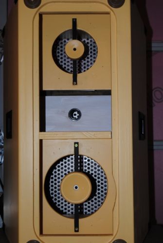 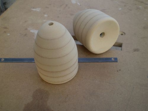 |
Posted By: kr1sounds
Date Posted: 29 March 2015 at 3:29pm

^^ 12 & 8 inch  ^^ 10 & 8 inch ------------- I MAN SERVE SELASSIE CONTINUALLY... NO MATTER WHAT THE WEAK HEART SAY fostonshfs.webs.com |
Posted By: piers1
Date Posted: 29 March 2015 at 6:57pm
| Note, those posted drawings by "kr1sounds" was my conceptual plans, has never got built. I ended up with the one I posted above. |
Posted By: kr1sounds
Date Posted: 29 March 2015 at 7:10pm
|
how do they sound? ------------- I MAN SERVE SELASSIE CONTINUALLY... NO MATTER WHAT THE WEAK HEART SAY fostonshfs.webs.com |
Posted By: piers1
Date Posted: 31 March 2015 at 9:20pm
Terrible bad.
|
Posted By: Thomas Hosker
Date Posted: 31 March 2015 at 9:58pm
|
This thread is confusing! Is there any measurements for this box yet? Looks great! Is it reaching the 120hz lower target you set? And this is a 10"? ------------- WWW.T8Audio.Com |
Posted By: kr1sounds
Date Posted: 31 March 2015 at 10:38pm
|
uploads/18250/Simon_3_way_Mid_Top_Rev02.pdf" rel="nofollow - uploads/18250/Simon_3_way_Mid_Top_Rev02.pdf - thats the final plan there ------------- I MAN SERVE SELASSIE CONTINUALLY... NO MATTER WHAT THE WEAK HEART SAY fostonshfs.webs.com |
Posted By: snape6666
Date Posted: 01 April 2015 at 10:53am
|
Yes meassurements would be interessting! piers1 are you kidding?^^ Or are they really not good?^^
|
Posted By: snape6666
Date Posted: 01 April 2015 at 5:10pm
|
piers1 what drivers did you use for the 10" version? Would be thankful if you tell me your setup =)
|
Posted By: piers1
Date Posted: 02 April 2015 at 5:29am
They sound terrible... according to my wife :-) Look, I have given a fish, and this forum has other members that can teach you how to fish. In reality here is how it works: Teach a man to fish, and he will sit in the boat and drink beer all day... |
Posted By: Gingerbuilder
Date Posted: 17 February 2024 at 8:29am
| Hi is there a higher quality image available for the 12”version please. |