Unity horn build
Printed From: Speakerplans.com
Category: Plans
Forum Name: New Projects Forum
Forum Description: Forum for new speakerplans projects, in memory of Tony Wilkes, 1953 - 2014
URL: https://forum.speakerplans.com/forum_posts.asp?TID=75922
Printed Date: 27 March 2026 at 11:02am
Software Version: Web Wiz Forums 12.08 - https://www.webwizforums.com
Topic: Unity horn build
Posted By: snowflake
Subject: Unity horn build
Date Posted: 04 February 2013 at 5:10pm
    haven't made any noise with it yet as I am rushing to leave on holiday. will post more next week... |
Replies:
Posted By: Lee In Montreal
Date Posted: 04 February 2013 at 5:22pm
|
Very interesting. Useable frequency range? |
Posted By: Teunos
Date Posted: 04 February 2013 at 5:42pm
|
Celestion mids and beyma cd10fe highs? ------------- Best regards, Teun. |
Posted By: snowflake
Date Posted: 04 February 2013 at 5:48pm
yep celestions and the 1.4" version of the beyma. predicted to do 280Hz to 16kHz |
 Teunos wrote:
Posted By: Phil B
Date Posted: 06 February 2013 at 11:21am
|
What size ports are you using with those Celestions? And what size are the Celestions? They don`t look like the TF0410MR`s we`re using in our Unities?? Also are you going to add an extra tap to get the box down lower? .p. ------------- Mostly harmless.... except if catering is shut. Solar Sound System Shennanigans.. http://diyhifi.biz/" rel="nofollow - http://diyhifi.biz/ |
Posted By: snowflake
Date Posted: 06 February 2013 at 12:26pm
the ports are 1" and the mids are 6". sims say the port speed should be ok. I've left room in the design for two 10" drivers but haven't worked out how to get wide bandwidth from them yet. as the sensitivity of the bottom section won't be great am thinking I might cover 70-280Hz with a separate front-loaded horn or ported horn.
|
Posted By: Phil B
Date Posted: 06 February 2013 at 8:59pm
|
I`d personally stick with keeping the 10"s in the Unity and get full range coverage from one source. You are using a sealed box already so have a rear volume to start with? Our Mkii horns will have 2 x 10" per box and will be slightly bigger than the Mki`s to allow the horn to work down to 100hz. It`s looking like the P-Audio SN 10 MB is the cheapest , best simming driver at the moment.... we`re still trying to get T/S parameters on all the weird and wonderful car audio drivers available here in Aus! Might be a contender hidden in there... .p. ------------- Mostly harmless.... except if catering is shut. Solar Sound System Shennanigans.. http://diyhifi.biz/" rel="nofollow - http://diyhifi.biz/ |
Posted By: snowflake
Date Posted: 06 February 2013 at 10:05pm
i've managed to get sims with response down to about 100Hz but I thought it should be possible to get lower than this? would like to get to 80Hz or 70Hz so they could be used as monitors. some of danley's designs claim to get response down to 50Hz with two 12" drivers. he seems to port the volume in front of the cone and the rear volume into the horn so I guess this is a 6th order bandpass. my boxes will have a sealed volume above and below the horn module and another volume to the sides and rear which could be connected if I make some holes through the vertical flare pieces. the photos don't show the back panel glued in yet. have you looked at faital pro 10hp1020"? - that's what I've been using in my sims have you got a link to your mkii horn?
|
Posted By: Phil B
Date Posted: 06 February 2013 at 10:21pm
|
We looked at the Danley porting method as well, it uses the rear volume then short tube ports back into the horn mouth so possibly a 6th order. We`ve done sims with simple ports under the front of the driver and rear not ported and ported on short tubes. Here`s unported 10" Ande and P-Audio in Mkii horn  And same drivers in ported  So 80hz is possible quite easily...getting the rear ported in phase and with good port velocity...that`s the trick! Mkii hasn`t been built yet but will be a 1m horn loaded with: 1 x RCF ND 2530 ( just bought these...super nice drivers!) 4 x Celestion TF0410MR (sealed back 4") 2 x 10" ( P-Audio or something else with low qts and high qms which seems to sim best) Hopefully in the next two weeks we`ll get a prototype done! .p. ------------- Mostly harmless.... except if catering is shut. Solar Sound System Shennanigans.. http://diyhifi.biz/" rel="nofollow - http://diyhifi.biz/ |
Posted By: snowflake
Date Posted: 07 February 2013 at 2:09pm
what voltage is your input for those graphs? is it parallel drivers into 4Pi? cheers Phil?
|
Posted By: Phil B
Date Posted: 08 February 2013 at 9:42am
|
Hi 2.83v and parallel into 2 pi ( I think as my mate Richie has the info on his laptop!). Those are just rough sims as we haven`t decided on the final rear volume or how we will port it back in ... .p. ------------- Mostly harmless.... except if catering is shut. Solar Sound System Shennanigans.. http://diyhifi.biz/" rel="nofollow - http://diyhifi.biz/ |
Posted By: CoblosBrengose
Date Posted: 09 February 2013 at 8:31am
Hi Phil Have you actually seen inside dsl box? From iso wire frame images on the dsl website there aren't tube ports..only simple holes |
Posted By: Phil B
Date Posted: 09 February 2013 at 9:24am
If you look at this wire frame from their site you can see that there are very short tubes on the rear ports coming in at the mouth end of the horn. And from looking at a front on view you can clearly see the driver on the cone side ports and that the other ports are extended?  This is probably to increase the path length etc etc and get everything in phase. Obviously where the rear ports enter the horn is the most critical measurement and the ports are just tuning the rear volume to the horn mouth. Danley has very cleverly split the outer box with baffles to increase path length inside the rear volume ... all very tricksy to try to replicate! .p. .p. ------------- Mostly harmless.... except if catering is shut. Solar Sound System Shennanigans.. http://diyhifi.biz/" rel="nofollow - http://diyhifi.biz/ |
Posted By: Phil B
Date Posted: 11 February 2013 at 12:58am
|
Found these snippets of info from DIY forums...so it does act as a 6th order bandpass but NOT to extend within the horn. Questions were asked about how the Danley SH50 can go down to 50hz when it`s horn mouth is so small and wouldn`t support horn loading down there. We were looking at extending our present horn out to get down to 100hz but seems we were barking up the wrong tree! JLH ... With the Danley Synergy horns the role of the woofers is a little different than most people think. In most of the Danley models the woofers take over from the mids at around 300Hz. They get horn loaded through entry ports just like the mids do from 300Hz down to about 135Hz. Depending on the model, 135Hz to 150Hz is all the mouth size will support for horn loading. Everything below the frequencies supported by horn loading is handled by bass reflex. In order to get the bass reflex section to match the sensitivity of the horn loaded section, the bass reflex is tuned up in frequency and made to peak in a narrow band. (When is the last time you’ve seen a pair of 12” woofers tuned to 80Hz?) So, you’re shooting for a very peaked reflex response to complement the horn loaded section. In normal life you would never design a bass reflex enclosure to behave this way because it would be a one note wonder. However, for the Synergy this is exactly what you need to extend the lower frequencies to exceed what is possible with the mouth size. Tom Danley ... Fwiw, the horn loading and effect of the low pass filters ends around 100Hz on an SH-50 (hard to separate it into the separate bits), the lowest part is the radiation from the ports which are short passages that extend to the rear and delay the driver’s rear signal which combined with the compliance form a stubby lumped tapped horn / vented box style acoustic phase. So the very short tubes are just to correct the rear bass reflex path length to get that peaked response... So back to the drawing board for us! Now we can do both parts of the driver in Hornres ...front as a standard Unity and the rear as a reflex ignoring the horn mouth...Hmmmm .p. ------------- Mostly harmless.... except if catering is shut. Solar Sound System Shennanigans.. http://diyhifi.biz/" rel="nofollow - http://diyhifi.biz/ |
Posted By: cravings
Date Posted: 11 February 2013 at 1:28am
| very interesting. |
Posted By: CoblosBrengose
Date Posted: 11 February 2013 at 1:41am
| I fail to see tube ports in SH46, SH64, SH69, SH96 |
Posted By: Phil B
Date Posted: 11 February 2013 at 2:56am
Yeah...and? I`m just seeing how they acheived the low extension and if need be you could add tube ports to tune the rear output. The picture above of the SH50 wireframe shows very short tubes ( possibly only just deeper than the horn moulding itself) . The frontal picture of the SH60 clearly show that`s the ports are longer than the horn moulding??? .p. edit...found this pic which was the one I was looking for originally... 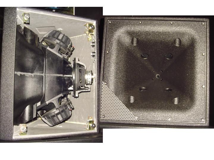 ------------- Mostly harmless.... except if catering is shut. Solar Sound System Shennanigans.. http://diyhifi.biz/" rel="nofollow - http://diyhifi.biz/ |
Posted By: snowflake
Date Posted: 11 February 2013 at 12:28pm
| it hadn't occurred to me that there was any horn-loading of the bass section going on. 1/4 wavelength of 150Hz is 56cm which is less than the length from bass tap to mouth. will try modelling as a ported horn (which I have designed before) and see what I get. usually in a ported horn the radiation from the two sides in inherently in phase because of the helmholtz resonator inverting the rear radiation - ports on both sides in going to screw up the crossover region. or is the port on the front of the driver tuned higher than the passband so the chamber is just acting as a LPF loading the driver into the horn and not affecting the phase??? |
Posted By: snowflake
Date Posted: 13 February 2013 at 1:07pm
|
currently waiting for cash flow to buy a speaker tester setup as this PC has no soundcard. but I have been listening to some music. have used the filter settings from my akabak model and adjusted them on the ultradrive till the treble level sounds right. HPF is 6dB at 1.5kHz the output fed back into inputC and another HPF 6dB at 4.1kHz. akabak model has LPF on the mids at 600Hz to flatten response and give roll-off at ~ 1.5kHz. have currently got the ultradrive LPF set at 1.14kHz as this sounds better. as the mid ports are at the edge of the cone probably getting cancellation across the diaphragm giving a steeper acoustic roll-off than predicted by akabak. sounds good - will get a martin audio 12"+1" next to it later to compare. |
Posted By: Phil B
Date Posted: 14 February 2013 at 9:15pm
|
We are running our Unities without any LPF on the mids with a passive crossover HPF and pad for the highs. The mids filter themselves pretty well on their own and adding a LPF seemed to screw with the phase. We got a pretty flat response and phase with a simple 2nd order crossover at 1.2k. Gotta be someone close to you that can lend you some measurement kit...I`m interested to see how your mids work out! .p. ------------- Mostly harmless.... except if catering is shut. Solar Sound System Shennanigans.. http://diyhifi.biz/" rel="nofollow - http://diyhifi.biz/ |
Posted By: snowflake
Date Posted: 14 February 2013 at 9:38pm
had a play with true rta signal generator, a cheap sound level meter and my ears. all tests were done in my bedroom - so obviously not very accurate. did find out a few things. mids are pretty flat from 200Hz to 1.2kHz. the predicted rising response from 600Hz to 1.2kHz isn't there and it rolls off nicely after that. so I could do without a LPF on the mids. have changed the HF filters from 6dB at 4.1kHz and 1.5kHz to 7kHz and 1kHz which is giving a flatter response at the same level as the mids. was expecting response to go to 16kHz but there isn't much above 12kHz - but maybe it's my ears going  . crossing the mids to bass at 200Hz rather than 280Hz has made the vocals sound a lot better. . crossing the mids to bass at 200Hz rather than 280Hz has made the vocals sound a lot better. |
Posted By: snowflake
Date Posted: 25 February 2013 at 8:34pm
done some A/B listening comparing my unity to a martin audio EM76. unity goes just as high and midrange is audibly clearer. EM76 sounds honky in comparison. going to add a couple of Beyma 10MI100 for mid-bass which should go down to 110Hz @ 108dB with 2.83V. then try and measure the impedance and design a passive crossover  should be a good box for about £400 in parts should be a good box for about £400 in parts  |
Posted By: Phil B
Date Posted: 26 February 2013 at 2:22pm
Nice....  Show us some pics.... Show us some pics.....p. ------------- Mostly harmless.... except if catering is shut. Solar Sound System Shennanigans.. http://diyhifi.biz/" rel="nofollow - http://diyhifi.biz/ |
Posted By: snowflake
Date Posted: 11 March 2013 at 9:34pm
|
got hold of a behringer ultracurve deq2496 and condenser mic and done some measurements on the box at the top of thread. unity horn is now +/-3dB from 200Hz to 18kHz apart from one on-axis dip at 3.5kHz. off axis there is some HF roll-off and the response around crossover (1.3kHz) dips a bit. it was a bit of a struggle getting the mid and high sections to meet due to earlier than expected roll-off of the 6" mids. after a bit of trial and error I have switched to 3rd order LPF at 2kHZ. the HPF is the product of a first order at 6kHz and second order at 720Hz. sounding pretty good but as it is in the middle of the vocal range the 3.5kHz hole is noticeable. akabak prediction says it should be beaming on axis slightly at 3.5kHz rather than two side lobes. have tried to model the inside of the compression driver better but my akabak simulation is not near enough to measurements to be useful for further fine adjustments. going to try narrowing the vertical flare angle by a couple of degrees and see what this does.
|
Posted By: snowflake
Date Posted: 14 March 2013 at 1:39pm
seems i'm suffering from something called high frequency fingering  due to incorrect horn termination due to incorrect horn termination 
|
Posted By: CoblosBrengose
Date Posted: 15 March 2013 at 7:05am
|
congrats snowflake my project stage: drawing board   |
Posted By: 4AC
Date Posted: 15 March 2013 at 10:45am
|
Wow very nice job on the Unity horns in Sketchup! Would you be so kind to share the sketchup model with us? You can upload/export it to the sketchup models database... Cheers ------------- uǝɿɿɐʌǝ6ɯo sı ʇsʞǝʇ ǝzǝp |
Posted By: bitSmasher
Date Posted: 15 March 2013 at 11:09am
oh my  |
Posted By: CoblosBrengose
Date Posted: 16 March 2013 at 2:20am
|
hi A4C that's only artistic depiction of my imagination based on the published photo on the DSL website, not a scientific / accurate model. the internal geometry of synergy horn is kinda mystery to me. I'm still learning to grasp it.
|
Posted By: Phil B
Date Posted: 17 March 2013 at 1:25am
Snap.... http://www.facebook.com/photo.php?fbid=600245400004843&set=o.126113687424773&type=1&theater" rel="nofollow - http://www.facebook.com/photo.php?fbid=600245400004843&set=o.126113687424773&type=1&theater Are you trying to back engineer from that photo? .p. ------------- Mostly harmless.... except if catering is shut. Solar Sound System Shennanigans.. http://diyhifi.biz/" rel="nofollow - http://diyhifi.biz/ |
Posted By: CoblosBrengose
Date Posted: 18 March 2013 at 2:57am
|
Hi Phil my drawing came first, I posted in diyaudio forum subwoofer section to illustrate 30 hz 6-fold TH designed by XOC1 in the March 12, and Ivan Beaver, the DSL lead engineer, released few days later on FB, March 15. I have purchased 8 Faital 12" few weeks ago. he use SH69 while my drawing is SH46-wannabe, which is narrower to allow 4 boxes to cover 180 deg. I must admit Mr. Danley is genius! the more I dug the more respect, how thoughtful his design is.
|
Posted By: Phil B
Date Posted: 18 March 2013 at 7:20am
|
Well here`s some more motivation for you.... we got busy today with our new prototype 3 way Unity...after doing a lot of reading and sims. It is a juggling act with Unities, whatever you do somewhere affects further down the chain. So after doing our mids we are hopefull we got the low mids right! http://forum.speakerplans.com/topic63191_post763223.html#763223" rel="nofollow - http://forum.speakerplans.com/topic63191_post763223.html#763223 .p. ------------- Mostly harmless.... except if catering is shut. Solar Sound System Shennanigans.. http://diyhifi.biz/" rel="nofollow - http://diyhifi.biz/ |
Posted By: Steve_B
Date Posted: 18 March 2013 at 1:58pm
Do you have any polar or on/off axis plots? I'm just curious how bad it is.
|
Posted By: snowflake
Date Posted: 18 March 2013 at 4:41pm
haven't got any plots but if i remember correctly was about 4dB dip about half an octave wide centred on 3.5kHz. clearly audible as you move from on-axis to off-axis. think I'm going to do a new prototype with bigger mouth and 60V*45H dispersion.
|
Posted By: Steve_B
Date Posted: 20 March 2013 at 11:36am
 The generally accepted principle is to double the flare rate over the last 1/3 of the horn. The following diagram is taken from Keele's paper on constant directivity horns.  |
Posted By: bwaslo
Date Posted: 20 March 2013 at 2:22pm
|
I ran into a similar dip on-axis on my 90x60 DIY Synergies. I'm pretty sure it was coming from diffraction off the larger ports (nearly went away when I blocked the ports with thick plastic tape). http://www.diygroup.com/forum/index.php?topic=19.msg895#msg895 - http://www.diysoundgroup.com/forum/index.php?topic=19.msg895#msg895 |
Posted By: grec
Date Posted: 21 March 2013 at 9:03am
Probably that's why I have way better HF when I move 1-or even 2 meters a side then when I sit in a front of speaker.
|
Posted By: snowflake
Date Posted: 22 March 2013 at 10:33pm
|
Steve, read the keele paper a few weeks ago. any idea how quickly fingering starts to appear as you make the mouth flare less than a 1/3. I was thinking of trying to get away with the last 1/5th - not least because it makes mounting the woofers a lot easier. I'm thinking it might be possible to have a smaller mouth with compromised horizontal dispersion that has some 'fingering' from a single box but when you array it the fingers of the neighboring boxes could be made to lie at different angles thus smoothing the polar response of the array. anyone tried this?
|
Posted By: Steve_B
Date Posted: 23 March 2013 at 3:57pm
|
The idea of the increased flare at the mouth is to reduce
edge diffraction. Ideally the mouth termination would be curved but that is
tricky with large ply horns. The hi-fi horn designers, where large round overs
are less impractical suggest that ideally the radius of the mouth termination
should be equal to one wavelength of the lowest frequency. Others consider that
a radius of ¼ wavelength is OK. One would expect that the mouth geometry would
affect the lower and mid-band of the horn more than the higher frequencies. The differences in
the high band can be due to the different degree of coherence presented by the
wave front at the compression driver’s exit. This depends on how the phase plug
geometry has been optimised. At very high frequencies a high-frequency driver can change
its radiating figure quickly depending on frequency. It is possible for it to
change from a plane wave, to a ring radiator or to a point source whose
effective dimension is smaller than the throat. These changes are reflected in
the wave front curvature, which can lead to driver>throat mismatching, and can
be a source of internal diffraction and distortion as well. Changing the drive
unit could significantly alter the amount of fingering a given horn exhibits. If you set up a grid across the mouth of the horn and
measure the pressure in each cell, the pressure variations show up like the
room mode patterns, with high and low pressure regions that change with
frequency. Keith Holland (Southampton Uni) did some work on
obstructions within the horn and if I remember correctly something on the left
hand wall creates an artefact on the right hand side. With a unity style horn
the mid apertures will be a source of problems. As with most design problems, it is a case of deciding which
features and compromises best fit your priorities. I would imagine that an array of unity horns would behave in a similar manner to a multicellular horn. It would be expected therefore that there will be a narrow lobe at the frequency where the width of the array is about one wavelength. Above that the pattern will widen and at high frequencies there will be some fingering |
Posted By: MarjanM
Date Posted: 23 March 2013 at 4:43pm
Can you measure this so we can see where the dip exactly is? I might have an answer to this but i will have to see the graph first to be sure i am not talking stupid things. ------------- Marjan Milosevic MM-Acoustics www.mm-acoustics.com https://www.facebook.com/pages/MM-Acoustics/608901282527713 |
Posted By: Steve_B
Date Posted: 24 March 2013 at 12:40pm
|
Just because your suggestion might not be the correct one in this specific case does not mean that it is stupid (unless it is just stupid generally ). Diagnostics at a distance is always a bit hit and miss. Please share, it might be of use to other forum members.
|
Posted By: MarjanM
Date Posted: 24 March 2013 at 12:45pm
|
Ok. The BMS4550 that danley use has a natural bump at 3Khz, so maybe they dont tame it as we do, and the result is a flatter line. ------------- Marjan Milosevic MM-Acoustics www.mm-acoustics.com https://www.facebook.com/pages/MM-Acoustics/608901282527713 |
Posted By: snowflake
Date Posted: 24 March 2013 at 5:30pm
|
steve, been reading this page about mouth termination http://sound.westhost.com/articles/waveguides1.htm#intro bit confused - the above says that when you add the flare the coverage angle becomes the average of the two wall angles. in keele's paper it doesn't mention this and the diagrams on page 20 and measurements on p23 suggest that the coverage angle is determined by the angle of the initial section and is not increased by the greater wall angle at the mouth. I lose track of the maths in the link above. about half way down after the big pencil symbol the text starts refering to angles a and b which do not appear in any of the formulas  I tried blocking off the mid holes on my horn with tape. there was a slight improvement in the HF response with the width of the dip decreasing slightly (1.5dB boost at 5kHz) but the minimum SPL at 3.5kHZ was not improved. this suggested to me that there was a second effect over-layed on top of the mid-holes effect. I think others may have found more problem with their mid holes as mine are relatively far from the horn throat. taping some material around the horn mouth both increased the SPL at 3.5kHZ by about 1.5dB and reduced the peak at 7kHz by 1dB giving a flatter overall response. I think I read somewhere that adding soft material at the mouth edges has a similar effect to adding a curved mouth flare. I will try doing this again with better materials than the socks and gaffer tape I had to hand
anyone have ideas on what thickness and width of material to try for optimal results? |
Posted By: Timebomb
Date Posted: 25 March 2013 at 1:10am
|
Id go with a rolled up towel, makes quite a big difference. The initial flare angle will dictate HF dispersion, the combination of the 2 flare angles will dictate dispersion further down. A HF wave can see a CD horn like 2 horns in series, depending on the abruptness of the change in flare rate. ------------- James Secker facebook.com/soundgearuk James@soundgear.co.uk www.soundgear.co.uk |
Posted By: _djk_
Date Posted: 25 March 2013 at 2:25pm
Clifford A Hendricksen "The Manta-Ray Horns" (co-authored with Mark Ureda), Journal of the AES, vol 26 no. 9, September 1978. ------------- djk |
Posted By: _djk_
Date Posted: 25 March 2013 at 2:41pm
 The inner angle controls the HF dispersion. The angle increases by 50% at 2/3rds the width (or height) of the mouth. IE: a H60° horn 30" wide increases to H90° at the point it is 20" wide. The original article at the JAES costs $20 for non-members, $5 for members. It is also in the JAES Loudspeakers Anthology Vol. 1 (448 pages), $40 for non-members, $30 for members. Try a university library if you have one nearby. I will update this post with the formulas for dispersion and size after I get some sleep. ------------- djk |
Posted By: snowflake
Date Posted: 26 March 2013 at 4:31pm
| thanks DJK, managed to download the manta-ray paper as well as a couple of other interesting looking ones that reference it. |
Posted By: snowflake
Date Posted: 26 March 2013 at 8:13pm
| going to change the throat in next prototype to include a smooth radius joining the angle of the compression driver exit to the horn wall angle. this adds about half an inch to the horn length. this could conceivably be one of the factors producing a hole in the response at 3.5kHz and should also help reduce harmonic distortion. |
Posted By: _djk_
Date Posted: 26 March 2013 at 8:30pm
|
I built these double 12 mids in 1980 after reading the manta-ray paper, they sounded much better than the Altec A7, JBL 4560 type enclosures that were popular at the time. http://i56.photobucket.com/albums/g196/dkleitsch/dual12MantaRay.jpg" rel="nofollow - http://i56.photobucket.com/albums/g196/dkleitsch/dual12MantaRay.jpg ------------- djk |
Posted By: snowflake
Date Posted: 29 March 2013 at 8:37pm
| I've sanded the horn throat to give a more gradual transition from compression driver throat angle to horn wall angle but it hasn't made any significant difference to the response. |
Posted By: snowflake
Date Posted: 02 April 2013 at 11:35pm
|
added more felt strip six inches wide and half an inch thick all the way round the throat. had to readjust the crossover slopes a bit and now seem to have got on axis response pretty flat. moving off axis the response curve pretty much keeps the same shape. response is now -3dB at 180Hz and 17kHz. in band response is +/- 2.5 dB with 1/6 octave resolution. adding felt to the edges is certainly easier than increasing the size and weight of the box by enlarging the mouth flange. the midrange response is damped down slightly by the felt but only about 1dB. would be good if the mids went a bit higher but pretty happy with the response. I did spend a long time designing this but quite surprised it has turned out so well. now for the ten inch bass drivers
|
Posted By: Steve_B
Date Posted: 03 April 2013 at 10:46am
Welcome to the world of design and experimentation. Some
things work, many don’t. It sounds like you are moving in the right direction
though. |

Posted By: snowflake
Date Posted: 20 June 2013 at 6:20pm
|
gave up trying to accurately model the bass section of the unity horn so just went for it and drilled some extra holes in the box at the start of the thread. I went for two beyma 10MI100 drivers because of it's strong motor, low Vas, compact size, reasonable power handling. two of them were predicted to be similar in sensitivity to the other two sections. tapped the front of the driver into the horn just over half way down the horn with two 36mm holes per driver. this seemed reasonable compared to the mid drivers which had a 1" hole per driver. measured the response and found the low section was giving a similar sensitivity to the top section with a bit of a peak at 350Hz and the first cancellation notch at about 450Hz. the low end had a gentle roll off to about 70Hz. the rear volume was about 12L per driver. two 36mm holes per driver through 12mm wood happens to give a predicted tuning of about 100Hz so went with this. response was now -3dB at 80Hz with a bit of a hump at 100Hz at a similar level to the one at 350 Hz. the dip in between was several dB. all these measurements have been done indoors so not that accurate especially for the bass. just using behringer mic and ultracurve. playing around with the filters I tried to keep them low order to reduce the number of components needed. 6dB per octave at 8kHz made the top section similar in sensitivity to the bass. 12dB per octave at 1kHz protects it from overexcursion and gives the max response at crossover. ended up having no LPF on the mids - they help out filling in a dip around 4.5kHz and it sounds more natural without a filter. HPF on mids is 6dB at 260Hz - the small chamber on the mids means there is no danger of overexcursion and LPF on bass is 12dB at 260 Hz which flattens out the upper bass region. acoustic crossover points are 350Hz and 1.2kHz. the three sections (1.4", 4*6", 2*10") are matched in sensitivity when the filters are set so the entire crossover network will be four caps and two coils with possibly a notch filter on the tweeter if needed. would be interesting to get some phase and impedance measurements but seem to have done pretty well without. sounds better than any other speaker I have listened to and doesn't need much eq to make it totally flat. bit of chuffing on the rear bass ports which might be solved by rounding the edges and the taps from the front side might work better an inch nearer the throat. will post a photo when I charge my camera up.
|
Posted By: snowflake
Date Posted: 21 June 2013 at 7:11pm
  |
Posted By: grec
Date Posted: 22 June 2013 at 11:05am
|
Nice!
|
Posted By: Phil B
Date Posted: 26 June 2013 at 11:56am
After all the modelling and predictions we did with our Unity box in the end we did just that...drilled holes and saw what we got! Getting a decent model seems only practical in Akabak..which I have no knowledge of... Curious as to why you put the 10" rear ports on the same horn face as it`s front ones? But it seems to work?? Good work ! .p. ------------- Mostly harmless.... except if catering is shut. Solar Sound System Shennanigans.. http://diyhifi.biz/" rel="nofollow - http://diyhifi.biz/ |
Posted By: snowflake
Date Posted: 26 June 2013 at 7:35pm
|
I was using akabak and wasn't getting anywhere - my model ended up so complicated I'm not sure I hadn't made an error somewhere. anyone know if it is possible to generate a 2D schematic from akabak script like you can in hornresp as a sanity check? anyway, the side walls of the horn continue to the top and bottom of the box seperating the rear volume of the woofers from some wasted volume that contains the mids and compression driver. the main reason for doing this was to make contstruction easier as the rear panel and vertical edges at the front of the cab don't need to be airtight. I guess if I had 12" drivers and wanted to go down to 50Hz then I would need the whole volume. think I may need to increase the 1.4" reflex ports up to 2" and put some 5cm tubes in as they seem to be chuffing at moderate levels. just been estimating the average sensitivity by comparing to some other boxes and would guess it is 104dB/2.83V and the impedance should be over 8R for all but half an octave of the operating range. waiting for the crossover coils to arrive. can't wait to get it outside to do some high power tests.
|
Posted By: MarjanM
Date Posted: 27 June 2013 at 12:47am
|
104db? Danleys box is 100db. ------------- Marjan Milosevic MM-Acoustics www.mm-acoustics.com https://www.facebook.com/pages/MM-Acoustics/608901282527713 |
Posted By: snowflake
Date Posted: 28 June 2013 at 10:08am
| danley's SH50 is -3dB at 50Hz whereas mine is currently tuned with -3dB at 80Hz. I am guessing he uses one of the Faitalpro 12" drivers which has considerably more xmax and lower BL than the beyma 10MI100 that I used. so mine should be more sensitive. there are no l-pads to match the levels of the drivers in my box - the crossover filters do it all. |
Posted By: AndyWave
Date Posted: 29 June 2013 at 5:20pm
|
Very interesting this whole thing. Hats off and ------------- torturing electrons since ...... |
Posted By: _djk_
Date Posted: 30 June 2013 at 10:39am
|
"Danleys box is 100db." He has many models, SH50=100dB SH64=103dB SH46=106dB SH25=110dB ------------- djk |
Posted By: snowflake
Date Posted: 02 July 2013 at 1:31pm
|
done some high power testing - was still indoors so not ideal but found some interesting stuff. first off i fitted a protection bulb and polyswitch in series as protection for the beyma cd1014fe HF driver. also fitted an 80uF cap as HP for the mids. still waiting for the coils to finish the passive network. filter settings are posted above. bulb is a 24V 50W osram halogen. cold resistance is 1.5R and calculated full power resistance is 12R - so ratio of cold to hot resistance is only 1:8 which is lower than usual. polyswitch is one of these: http://www.te.com/catalog/pn/en/887538-000" rel="nofollow - http://www.te.com/catalog/pn/en/887538-000 played around turning the volume up quickly and the polyswitch seemed to cut out at moderate volumes before the bulb started glowing as planned. played a few tracks at full volume with earplugs in as it was insanely loud. was putting 3*800W amp channel into 1.4",4*6", and 2*10". at higher volumes there was a lot of colouration of the upper treble and severe chuffing from the reflex ports. examining with the mic and signal generator confirmed this. frequencies above 5kHZ showed high levels of distortion up to 20kHz at a level approaching -10dB of the signal at high volumes. the chuffing distortion was coming from the ports from the rear of the bass drivers. the output from 120Hz to 260Hz from the other ports did not have significant distortion even at full volume. the mids seemed relatively clean but might try making the shorts shallower to increase HF extension. the beyma cd1014Fe was the cheapest 1.4" I found so have ordered a Paudio BM2-D740 for comparison. going to try some flared 2" port tubes rather than the current 36mm holes to reduce the chuffing. will have it out at St Pauls carnival in Bristol if anyone is interested.
|
Posted By: snowflake
Date Posted: 09 July 2013 at 12:21pm
|
got the new compression driver and ports fitted for carnival. didn't get set up early enough to do very much fiddling but got it eqd flat. by the end of the day had it near full volume with the protection bulb lighting up pretty constantly and it didn't sound distorted as with the cheaper driver. old compression driver shown for comparision: http://s75.photobucket.com/user/philpope/media/P1010194.jpg.html" rel="nofollow"> 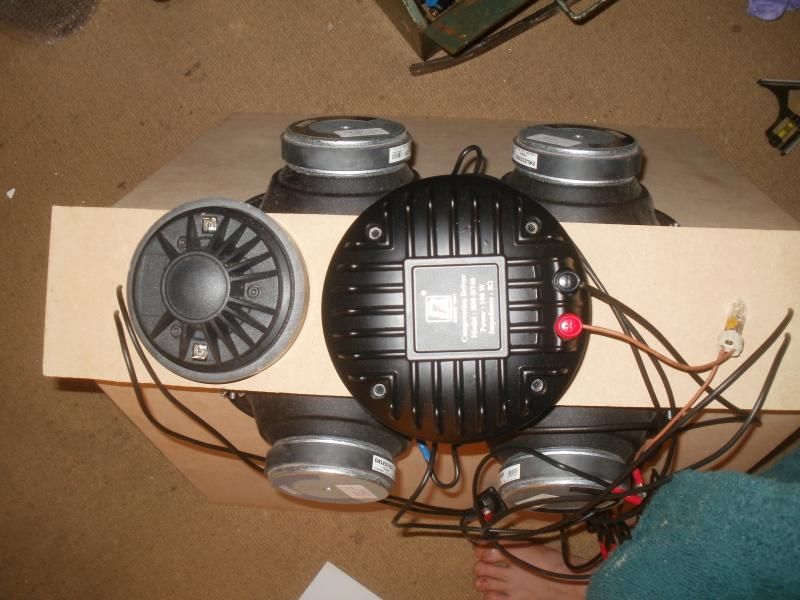 http://s75.photobucket.com/user/philpope/media/P1010207.jpg.html" rel="nofollow">  |
Posted By: snowflake
Date Posted: 23 December 2013 at 11:26pm
just finished new prototype (apart from the crossover)  those aren't quite the finished article as I have since added flying point brackets and handles.
|
Posted By: bee
Date Posted: 23 December 2013 at 11:28pm
|
nice work.... ------------- https://www.elements-audio.com |
Posted By: snowflake
Date Posted: 23 December 2013 at 11:34pm
|
about 75% of the box is made from laminated ply and mdf hence the different woods showing inside the horn. it seems to ring a lot less when you hit it - will see how it sounds when I do listening tests. I have abandoned using tee-nuts. a coach bolt with a couple of normal nuts and a washer works fine and if it does start to spin the nuts and end of the bolt are always on the driver side and accessible to pliers. this was the most complex build I have ever done but seems to have turned out well thanks to my new festool saw and guide rails. I just used PVA on most of it as the joints were so close polyurethane didn't seem necessary.
|
Posted By: Lee In Montreal
Date Posted: 23 December 2013 at 11:38pm
|
I definitely want to hear from you how well the "point source" works on that cabinet. |
Posted By: grec
Date Posted: 24 December 2013 at 11:37pm
Beautiful!
|
Posted By: Phil B
Date Posted: 25 December 2013 at 10:51pm
|
Nice work.....! How did the rear port of the woofer end up? I see you have extended the path by going to the edge of the outside box with the woofer baffle ? .p. ------------- Mostly harmless.... except if catering is shut. Solar Sound System Shennanigans.. http://diyhifi.biz/" rel="nofollow - http://diyhifi.biz/ |
Posted By: tv00
Date Posted: 26 December 2013 at 12:06pm
|
WHOW! Good work! Is there any difference in the new prototype from the old one? This year I've been digging top builds, amazing what people are doing! -It is good to see a unity horn build! |
Posted By: all bass
Date Posted: 26 December 2013 at 12:48pm
|
Looks good! Good to see that people are still building and experimenting different stuff! ------------- https://www.instagram.com/my_modular_journey/ |
Posted By: snowflake
Date Posted: 31 December 2013 at 12:57pm
at the moment the rear woofer ports are the same size as the front woofer ports. the response is falling off at about 100Hz and then there is a shelf that extends down to 40Hz. I think if I make the ports about 50% bigger should raise the tuning and the output of the port to make it -3dB at about 65Hz. major differences from the first prototype are that there is no wasted volume inside making the rear volume of the woofers much bigger. have used 12" rather than 10" woofers. changed the throat geometry a bit so that it is an exponential expansion which matches the compression driver throat angle at one end and the angle of the conical horn at the other. response of the new compression driver is very different to the BM-D740 which means re-design of the crossover. a compression driver that rolls off a 6dB per octave from 1kHz can easily be made flat with the right capacitor but the new driver is fairly flat to 7kHz anyway.
|
Posted By: snowflake
Date Posted: 31 December 2013 at 1:00pm
| by the way, Phil, hear you were at the Combat Wombat gig at my local in Bristol a few months ago. Think you were chatting with my friend Nate from Kebele Sound LOL |
Posted By: snowflake
Date Posted: 10 January 2014 at 1:09pm
|
crossover finished third order filter into L-pad with 12kHz HF bypass. bulb protection on tweeter with low value polyswitch in parallel for low level operation in case of bulb failure. small value caps paralleled with large ones to bring values within 1% of design. the resistors are rated at 30W each without a heatsink - may upgrade to some that are 50W or use even 6*50W so that the L-pad can dissipate a full 300W when the driver+bulb is drawing 100W - but maybe this is overdoing it when duty cycle and thermal mass of the resistors is considered??? also just received pre-wound coil that looks a bit tidier than my attempt. haven't got any LPF on the mids as this gives flatter response at 4kHz for some reason- perhaps coupling between mids and tweeter compensating for the hf 'suckout' of the mid ports. bi-amped with the woofers on one channel and mids/high on other channel. active 3rd order LPF at 130Hz and HPF at 280Hz with the phase of the mid/high section reversed gives flattest response. been running it off a crown xe4000 which can put 1200W into 4R for the woofers and 800W into the mids. haven't got it near clipping yet as the whole house starts vibrating
 |
Posted By: jamieb
Date Posted: 11 January 2014 at 6:06am
| I'd love to hear it |
Posted By: Phil B
Date Posted: 13 January 2014 at 1:26am
I was.... very briefly ! Managed to cobble together an almost OK sounding rig out of what was in the pub ( and what I made them go fetch !). Monkey Marc from Combat W is one of the other bods involved with our Solar/ Wind rig... Glad to see your project ticking along. We have been running our 3 way Unities for a few months now and all we get is compliments about the sound. We did a small stage at an outdoor festival on New Years day and pretty much wowed everyone there ( so much so we dragged it to the VIP area and did a 2 day after party!). I can`t explain to people how good they sound and the way a Unity horn images a true point source...you have to hear it ! The main stages had ground stacked L`Acoustic Kudo with SB28 subs and sounded horrible.... maybe we should offer to do it next year ! We are still running our mid/high crossover with a simple HPF for the Highs and no LPF for the mids like yours, but everything else is through the Ultradrive . The next step is a better crossover ( hopefully a BSS388 I have my eye on! ) and then maybe some 18" tapped subs with barn doors for next year ! Along with an MPPT controller for the wind genny! It`s never finished ........ .p. ------------- Mostly harmless.... except if catering is shut. Solar Sound System Shennanigans.. http://diyhifi.biz/" rel="nofollow - http://diyhifi.biz/ |
Posted By: fat_brstd
Date Posted: 13 January 2014 at 11:17am
I'll have one of your ultradrives if your getting rid of them. HAHA. BTW Snowflake, those unitys look really nice. Very good work. I also second what Phil said about not really being able to explain their coherence and having to hear them for yourself as nothing else comes anywhere near as close to a true point source, its actually quite strange to listen to the first time as you swear your hearing it wrong, or at least thats what happened to me. ------------- Melbournes Rootical Warrior Roots - Dub - Steppers http://www.facebook.com/adrians.wall" rel="nofollow - facebook page |
Posted By: snowflake
Date Posted: 12 September 2014 at 5:22pm
finished crossover at last after late delivery of capacitors and two wrong deliveries of heat-sinks. same as the one posted above but better components and a lot neater. had to mount the L-pad heat-sink separate to the rest of the crossover because of lack of space. connector strip is rated 41A with wire protectors under the screws. four more to make now :)
|
Posted By: TONY.A.S.S.
Date Posted: 12 September 2014 at 6:24pm
|
It's quite time consuming isn't it. ------------- http://www.facebook.com/tony.rossell.3" rel="nofollow - http://www.facebook.com/tony.rossell.3 |
Posted By: billy.jukes
Date Posted: 04 November 2016 at 1:14pm
|
Hello Phil, Do you still have this old synergy horn? I'm developing my own and would love to hear it. I also live in Bristol. Cheers,
|
Posted By: snowflake
Date Posted: 04 November 2016 at 1:24pm
| Hi, yes could meet up. you got a van and somewhere good to listen to them? |
Posted By: billy.jukes
Date Posted: 04 November 2016 at 7:29pm
| I could try and sort out using the malcom x for a listen. How many do you have and what do you have to fill the lf range? |
Posted By: billy.jukes
Date Posted: 04 November 2016 at 7:32pm
| I'll try and get my hands on a c7 rig as a reference point aswell |
Posted By: snowflake
Date Posted: 05 November 2016 at 5:47pm
| yeah Malcolm X if you can swing it - going there tonight as it happens. Can probably get in the Black Swan if not. Only got a pair of tops loaded up at the moment and 4*18" tapped horns. |
Posted By: snowflake
Date Posted: 11 August 2019 at 11:48am
|
old crossover left, new version right (designed with more accurate REW data). HPF shifted up to 1.5kHz and changed to second order rather than third (plus polarity reversal on tweeter). got rid of bulb and high-shelf bypass cap - rather implement these in LMS. series resistor and PTC moved to amp-side of filter inductor to protect whole circuit from over-powering. large cap is DC blocking and signal for both 6" and 1.4" now goes through it. same resistor network used as previously posted.  |
Posted By: snowflake
Date Posted: 11 August 2019 at 12:54pm
|
is coil too close to the tweeter? it is 3.3mH (though measures only 2.9mH). it's a neo tweeter.  |
Posted By: odc04r
Date Posted: 12 August 2019 at 11:57am
|
I wouldn't have thought that the coil's field would significantly affect the presumably much more intense field in the tweeters gap. What average current do you estimate the coil is seeing during typical use? The majority of a coil's magnetic field is inside it along the central axis, outside field strength is weak in comparison. |
Posted By: snowflake
Date Posted: 12 August 2019 at 12:22pm
|
without digging out old Akabak model (and old computer to run it) I am not sure. would the peak current through the coil be at the crossover frequency? and equal to the current through the driver? so about 1.5A max and much less at other frequencies. |
Posted By: studio45
Date Posted: 12 August 2019 at 1:04pm
|
As I see it, with the two components in the orientation shown, the tweeter's external field lines will be parallel to the mounting board, while the coil's will be perpendicular. So they are not particularly well set up to couple. There may be a very small modulation of the tweeter's magnetic field, and the coil will experience some mechanical forces as current passes through it - this will probably introduce a minor amount of distortion, but likely at a level far below other sources of distortion. ------------- Studio45 - Repairs & Building Commotion Soundsystem -Mobile PA |
Posted By: odc04r
Date Posted: 12 August 2019 at 1:13pm
|
Yup I agree with that assessment. I usually model xovers in Spice as well as Akabak if I'm trying to integrate them fully into a design. Spice is so much better for estimates of power dissipation as a function of frequency etc and I find helps when sanity checking. Peak current through the coil is going to depend on a few factors including musical content and the crossover design. Hard to say.
|
Posted By: snowflake
Date Posted: 19 August 2019 at 11:39am
|
measurements of old vs new crossover. on axis and 25 degrees off axis. old: green and blue, new: red and orange. smoothed 1/3 octave. ignore below 400Hz as measured in small room due to rain. much improved. mid-range lobbing isn't too extreme and expected high-frequency fingering above 3kHz is acceptable. I was having to do quite a lot of corrective eq with the old crossover (obviously too much vocal). with the new crossover it sounds pretty nice with no eq at all. next will try and play around with splay angles. see below for response plot
|
Posted By: odc04r
Date Posted: 19 August 2019 at 12:46pm
|
Yep, nicely damped the peak at 1KHz, much smoother roll off now and aintegrates well with the top. Hows' the phase looking? I'm still extremely keen to build a pair of Unitys but being realistic it's going to be years before I get to the final and finished items. But I can start with the mid/high portion of the design. I'm considering 3D printing the horn/mid assembly and then integrating that with a wooden cabinet with the low mids.
|
Posted By: snowflake
Date Posted: 19 August 2019 at 1:54pm
|
if you can 3d print the tweeter and mid mountings it will save a lot of woodwork and allow you to play around with chamber volumes and port shapes that just weren't practical with a router and rail saw. PM me if you want the CAD drawings of what I built as a starting point.
|
Posted By: snowflake
Date Posted: 19 August 2019 at 2:03pm
forgot to switch on the active filter - 3rd order LP and HP @350Hz. mid/top output inverted and delayed 33cm phase (old green, new red)  group delay 
|
Posted By: odc04r
Date Posted: 19 August 2019 at 10:10pm
That was my thinking, good for prototyping. I was also wondering if extending the port length to the mid chambers such that they were time aligned to the HF diaphragm could be of any practical value. Cheers for the CAD offer, maybe sometime in the future. I've already spent a while trying to flatten 3D CAD models of Unity horns into sheets for cutting - it's surprisingly non trivial. Not a typical use of CAD but there are ways. The plan in the meantime is to upgrade the CNC to a 4x2 ft bed and then I can just run the sheets off and finish them with a table saw to give near perfect results with minimum effort. It's not strictly needed but I'm going to do it anyway so why not use it. No obvious discontinuities in the phase with either xover but the newer does appear to have a more linear slope up to 2k so hopefully that leads to better mid-tweeter integration |
Posted By: snowflake
Date Posted: 05 April 2021 at 2:29pm
I now realise that using a DC blocking cap is a really bad idea because it removes all electrical damping at low frequencies. fortunately the HF and mid drivers are also protected by the cutoff frequency of the conical horn which increases the nearer to the throat you get, and by the rear chambers of the drivers. so with that removed the crossover is just a second order filter on the compression driver, an L-pad to match the levels and a protection fuse. Everything else is done by the horn geometry, front chambers, and tap sizes. In this case the midrange roll-off turned out very close to target without any electrical components, if not a series inductor can be used to modify the response of a FLH as explained in Kolbrek (though it is probably as quick to find the optimal value by trial and error than go through the theory). The acoustic LPF of the unity mid is one order higher than a FLH because of the cancellation of the reflection to the horn throat - so fourth order which matches the 2nd order acoustic and 2nd order electrical high pass filters applied to the compression driver. |
Posted By: Teunos
Date Posted: 06 April 2021 at 3:15pm
|
This one you need to explain to me; why would electrical damping at low frequencies be a problem if you insert a DC blocking cap? Off course presuming that it is really meant as "last resort HPF protection in case i insert the wrong speakon" or "my amp crapped the bed and really put out DC on the speaker output", or maybe "I wrongly configured the output matrix mixer of my DSP and sent bass to the tweeters". (which are the 3 primary reasons i use them on all HF drivers).
DC blocking cap HPF corner frequency should be chosen well below the intended passband of the speaker. As long as you maintain that rule (I suggest at least an octave below the intended passband), there is absolutely no noticeable impact on damping factor whatsoever.
------------- Best regards, Teun. |
Posted By: fatfreddiescat
Date Posted: 06 April 2021 at 4:18pm
| With a blocking cap the comp driver is partially decoupled from the amplifier due to the series impedance. This could be a problem due to the comp sharing a waveguide with the mid drivers as the SPL is very high at the throat of the waveguide, the pressure from the mids can cause the comp diaphragm to modulate excessively potentially damaging it. By coupling it directly to the amp or having a low impedance path across it's terminals, the diaphragm will be better damped and should help to reduce the modulation. |
Posted By: snowflake
Date Posted: 07 April 2021 at 12:32am
the compression drivers have an inductor across them so they will be damped at low frequencies. It is the mids I was worried about as cap was between them and the amp. Unless you are using amps that are clipping badly and putting out DC, the DC blocking caps will not help and possibly make things worse. My amps have clip limiters and enough headroom that they never clip anyway. |
Posted By: pappdani7
Date Posted: 26 October 2022 at 8:36pm
|
Hello! Perfect work! Could you share the plans of the speaker?
I would like to build my own so i would gladly pay for it as well. My email address: mailto:pappdani7@gmail.com - pappdani7@gmail.com Thank you very much! |