
|
Signal chain overload effects |
Post Reply 
|
Page <1 3456> |
| Author | |
audiomik 
Old Croc 

Joined: 06 April 2010 Location: Bath, UK Status: Offline Points: 2956 |
 Post Options Post Options
") Thanks(1) Thanks(1)
 Quote Reply Quote Reply
 Posted: 06 April 2012 at 2:58pm Posted: 06 April 2012 at 2:58pm |
|
Think it might be appropriate to look at what these clipped signals do at the 'end' of the signal chain as a whole.
Firstly there is no Limiter built which can re-construct the original waveform from a clipped one. Now with squarewaves you immediately have 1.4 times the RMS Voltage of the same peak Voltage sine wave or 3dB increase (twice) in Power from your Amplifier. Remember Power is proportional to V², so 1.4 x 1.4 = 2 which is where the doubling of the Power output of the Amplifier is calculated. Next we have very much the equivalent of a continuous signal so the 'Speaker rating which applies should be the Continuous Power value - not the Program Power value which assumes a much greater crest factor for the signal. Clipping has removed most of the crest factor. So back to Limiting to try to reduce the potential for 'Speaker damage occurring. Set the Amplifier input level to full (tamper-proofing) and then monitor it's output to match your 'Speaker's Continuous Power rating less 3dB. Set your LMS or other Limiter to 'brick-wall' at this level..... Might preserve your 'Drivers for another session, but be aware of the increase in HF content as shown earlier in this thread Hope this explains things reasonably! Mik |
|
|
Warning! May contain Nuts
plus springs, washers, screws, etc, etc. |
|
 |
|
|
snafu
Registered User 
Joined: 17 November 2008 Location: wales uk Status: Offline Points: 352 |
Post Options
Thanks(0)
Quote Reply
Posted: 06 April 2012 at 4:09pm |
|
Good read Mik, nice to see evidence of what our lugs are telling us.
|
|
|
|
|
audiomik
Old Croc
Joined: 06 April 2010 Location: Bath, UK Status: Offline Points: 2956 |
Post Options
Thanks(0)
Quote Reply
Posted: 08 April 2012 at 4:22pm |
|
Re: "In both venues thy now have NO fire alarm interface"
seem to remember this being a condition of Licenses? Mik |
|
|
Warning! May contain Nuts
plus springs, washers, screws, etc, etc. |
|
|
|
|
Muckerbarnes1
Old Croc

Joined: 20 March 2010 Location: Stroud Status: Offline Points: 2637 |
Post Options
Thanks(0)
Quote Reply
Posted: 08 April 2012 at 4:32pm |
|
In most cases yes.
However it is not always checked, yet alone installed. I find it varies from area to area, and fire officers vary too. I have tried to fit a Formula Sound AVC2 even thought there is a DBX processor. AVC2 is easy to interface to a fire alarm. The crud that comes out of the Pioneer with Traktor/Serato makes the AVC2 limit well early. Play a CD on normal and all is well. Introduce laptop.... and it limits. Just a load O crap!
|
|
|
Billy Dawg.
|
|
|
|
|
audiomik
Old Croc
Joined: 06 April 2010 Location: Bath, UK Status: Offline Points: 2956 |
Post Options
Thanks(0)
Quote Reply
Posted: 17 April 2012 at 4:17pm |
|
Test results for a Formula Sound FSM 600 Mixer.
In the first two pics, Line input is overloaded by providing a large three tone input signal, the same as for earlier tests:  This pic shows the Mixer set to have one red LED showing on the Output metering, note the position of the Fader on Channel 2 which is used as the test input being very low. Next the Input and Output signals, upper trace showing the output with clipping:  Now by selecting PFL for the input channel, this is clearly overloaded as the metering shows: 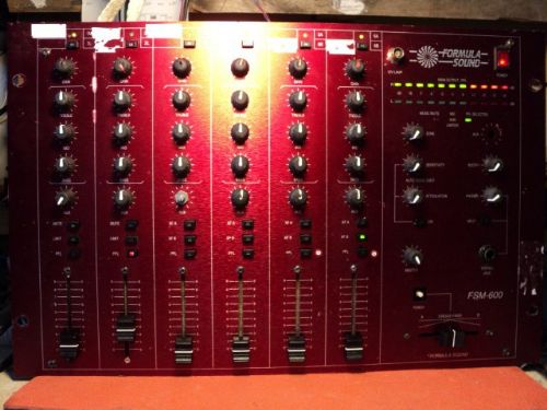 At least with this Mixer there is a very good chance of finding overloaded inputs and being able to do something about it! Mik |
|
|
Warning! May contain Nuts
plus springs, washers, screws, etc, etc. |
|
|
|
|
audiomik
Old Croc
Joined: 06 April 2010 Location: Bath, UK Status: Offline Points: 2956 |
Post Options
Thanks(0)
Quote Reply
Posted: 02 August 2012 at 3:40am |
|
If anyone has other samples of Mixers to test, it is fairly to set up a repeat of the tests used earlier in this thread.....
Other parts the signal paths can also be analysed further; should members have questions about this Mik |
|
|
Warning! May contain Nuts
plus springs, washers, screws, etc, etc. |
|
|
|
|
audiomik
Old Croc
Joined: 06 April 2010 Location: Bath, UK Status: Offline Points: 2956 |
Post Options
Thanks(0)
Quote Reply
Posted: 02 August 2012 at 3:56am |
|
If anyone has other samples of Mixers to test, it is fairly easy to set up a repeat of the tests used earlier in this thread..... a DJM800 anyone?
Other parts of signal paths can also be analysed further; should members have questions about this. Mik |
|
|
Warning! May contain Nuts
plus springs, washers, screws, etc, etc. |
|
|
|
|
scott_fury
Registered User
Joined: 28 October 2012 Location: Bristol Status: Offline Points: 329 |
Post Options
Thanks(0)
Quote Reply
Posted: 11 July 2014 at 3:36pm |
|
I'm hoping to have some clarification as to whether I understand how a distorted signal at the input stage affects the drivers at the end. This is where I am....
Firstly... The maximum output of the mixer is the amount the peaks can go above the average level before they get clipped. I'm assuming the headroom of a mixer is fixed. When monitoring the input of a signal are you only seeing the average level (nominal level?)? I'm guessing that there are peaks and spikes that do not get registered on the metering of a mixer? Secondly.... Clipping the peaks of a sine wave makes it more characteristically like a square wave, and this has more of a negative effect on a driver? There is more energy in a square wave, or is it the shape of the peaks? Finally... If the power of a distorted signal coming from a mixer can be greater when it reaches the LMS/amp, and this extra energy can still reach the drivers when the levels of the LMS and amp have been adjusted to stop clipping, how does this energy manifest itself at the drivers, e.g. movement or heat? Edited by scott_fury - 11 July 2014 at 3:37pm |
|
|
|
|
audiomik
Old Croc
Joined: 06 April 2010 Location: Bath, UK Status: Offline Points: 2956 |
Post Options
Thanks(0)
Quote Reply
Posted: 11 July 2014 at 6:34pm |
|
Scott
Firstly: with mixers, they usually have a nominal output level. This unfortunately varies between manufacturers and is monitored with some form of output metering. Now to fully detect peaks, special circuitry is used, the 'standard for this' is the Peak Program Meter, which can display either using bar-graph Leds or a special meter movement. The rise-time of these PPMs are specified by the BBC, but they still will miss very fast transient peaks. VU type metering is more common. Specifications for these comes from Bell Laboratories. These are much worse for showing short duration transient peaks There are various other types which don't follow any particular standard so we don't know their accuracy when reading signal peaks. The actual mixer output signal level then is taken from a continuous signal level indicated by an 0dB indication on the metering. The headroom above this nominal output level to maximum output, is the 'reserve before clipping' for the signal when peaks occur above the nominal level. Secondly: You are generally correct on this. The important thing when clipping occurs is that the Power of the signal increases whilst the peak Voltage remains the same. Also there is an increase in High Frequency content from the distortion components. Have a look at the spectrum displays for 'normal' and clipped' signals in post 2 of this thread - each spike in the spectrum display is one frequency detected. Finally: Most of this is already covered but with a signal of increased Power and very low crest factor, as with a clipped signal, plus added harmonic content isn't good for Drivers. A squarewave signal of the same amplitude as a sinewave one has a 3dB increase in Power or twice! See page 2 posts 1 and 2 for sample results of an LMS output for the same signal, at normal level and overloading an input. hope this answers you! Mik |
|
|
Warning! May contain Nuts
plus springs, washers, screws, etc, etc. |
|
|
|
|
scott_fury
Registered User
Joined: 28 October 2012 Location: Bristol Status: Offline Points: 329 |
Post Options
Thanks(0)
Quote Reply
Posted: 11 July 2014 at 7:47pm |
|
That's great Mik. Thanks for taking the time to reply. Any chance you could explain about what happens when the power of the signal increases but you say the voltage remains the same? I'm assuming that the impedance doesn't change, so it would be the current?
Also, when setting up my system I have usually put the amp volume up full, the mixer on 0db and bring the limiters on the LMS down to stop clipping on the amps (before connecting the drivers I may add!). How do these limiters differ from the clipping of a mixer for example? Edited by scott_fury - 11 July 2014 at 7:47pm |
|
|
|
|
audiomik
Old Croc
Joined: 06 April 2010 Location: Bath, UK Status: Offline Points: 2956 |
Post Options
Thanks(0)
Quote Reply
Posted: 12 July 2014 at 9:00am |
Scott voltage of a signal is measured as the RMS value of Voltage for Audio low level. Peak Voltage then is 1.414 times this value. When a sinewave is clipped the RMS Voltage approaches the Peak level of the sinewave such that the Power increases up to a factor of 2 when a full squarewave is reached. Thus the Power into a fixed load Impedance can double - current also increases pro-rata. Equally applies to program signals in the same way such that the delivered Power increases but the peak Voltage remains the same when clipping occurs. Another explanation relates to a somewhat complex maths approach! Also see Post 1 in this thread? You are using a good methodology for your setup. However Limiters shouldn't themselves clip a signal unless you overload their inputs or overdrive their outputs. Limiters use 'Gain Cells'* which are controlled by signal level to reduce their output depending upon how they are set. Hopefully they don't add any appreciable distortion. Clipping within a Mixer is simply that a signal amplifier stage reaches it's limit - usually just below the power supply voltage(s) - so has 'run out' of headroom Mik *different method but same result with DSP |
|
|
Warning! May contain Nuts
plus springs, washers, screws, etc, etc. |
|
|
|
|
scott_fury
Registered User
Joined: 28 October 2012 Location: Bristol Status: Offline Points: 329 |
Post Options
Thanks(0)
Quote Reply
Posted: 14 July 2014 at 8:37pm |
|
Thanks Mik. I'm slowly getting to grips with it.
Been a DJ for twenty years and have always been respectful of the levels, but the guy I'm currently teamed up with is notorious for giving soundmen shit when turning the gain to max. I'm a bit wary to leave him alone with my setup, hence my curiosity regarding clipped mixer levels, and seems that there isn't a solution, other than to stand over his shoulder for the duration of his set  |
|
|
|
|
Post Reply
|
Page <1 3456> |
| Tweet |
| Forum Jump | Forum Permissions You cannot post new topics in this forum You cannot reply to topics in this forum You cannot delete your posts in this forum You cannot edit your posts in this forum You cannot create polls in this forum You cannot vote in polls in this forum |


 Topic Options
 scott_fury wrote: