
|
Damping material in scoops |
Post Reply 
|
Page <12 |
| Author | |
JPF 
Registered User 

Joined: 20 May 2017 Status: Offline Points: 51 |
 Post Options Post Options
") Thanks(0) Thanks(0)
 Quote Reply Quote Reply
 Posted: 23 September 2025 at 5:12pm Posted: 23 September 2025 at 5:12pm |
|
Do you have anything positive to contribute to this topic? If not, it’s very rude to imply that there is something stupid in the opinions, answers, or information being politely exchanged among the other members. That kind of post clearly shows your own stupidity and desire for attention.
Edited by JPF - 23 September 2025 at 5:43pm |
|
 |
|
|
fudge22
Registered User
Joined: 26 July 2022 Location: UK Status: Offline Points: 263 |
Post Options
Thanks(0)
Quote Reply
Posted: 23 September 2025 at 9:37pm |
|
First off, I understand that scoops work on some magical principle, that only the initiated understand. My comments therefore concern rear loaded horns; i.e. an enclosure where the back of the diaphragm is horn loaded, and the front of the diaphragm faces forward on a baffle, which has somewhat of a similar outward appearance to scoops. I may not be the best person to say how much of the following might be relevant to the OP's loudspeaker.
Option for what? What are you trying to achieve by adding or changing the damping material in your cabinet? Are you just adding it because you have read that it is needed? A solution can be better determined once the problem is known. The absorption properties of a material are not directly related to the density of the material. If sound absorption is the main criterion of your choice, the figure that you need is the sound absorption coefficient, in the frequency range required. I’m not sure about scoops, but the idea behind the rear loaded horn was to increase the efficiency at low frequencies where the natural response of the drive unit was rolling off. The enclosure can be split into three overlapping regions. At very low frequencies (just what frequency is considered low depends on the size of the horn mouth and horn length) the enclosure behaves like a transmission line. As the frequency rises the behaviour transitions into that of a horn. As the frequency continues to rise, the relative level of the front to rear radiation becomes closer and, where path length differences cause the signals to be out of phase, destructive interference and thus an uneven response ensues. It is not uncommon to see large dips in the response of rear loaded horns. The aim of a good design is to have the horn’s response to roll off before it gets to the point where interference occurs. This can be done either by designing the rear chamber, which acts as a shunt capacitor, to act as a low pass filter at an appropriate frequency **, adding a thin layer of absorbent material for the placebo effect, or setting the crossover frequency below that where the response starts to suffer. The latter sort of defeats the object of using a rear loaded horn, where the front facing drive unit is supposed to give a useful response into the mid range, which is the frequency range where any absorbent material behind the drive unit will have most effect. If your design suffers from an uneven response at the upper end of its range, given that destructive interference, from path length differences, occurs at discrete frequencies, the best form of absorption, in my opinion, would be resonant. I have never seen this done though, and never a fan of rear loaded horns, something I have never tried. Resonant absorption could be achieved by incorporating a resonant chamber close to the throat of the horn, which is tuned to the problematic frequency **, as shown below. Should anyone try such a thing you are on your own in experimental territory. 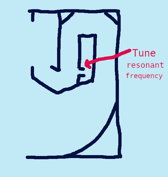 Anyone remember the Bassmax cabinet by Rhino Audio (if I remember correctly). It was like a rear loaded horn but with the drive unit in the back of the enclosure.
** I’d normally include the relevant formula, but I don’t think that they are applicable for scoops. |
|
|
|
|
mint
New Member 
Joined: 19 July 2015 Location: US Status: Offline Points: 9 |
Post Options
Thanks(0)
Quote Reply
Posted: 26 September 2025 at 4:31pm |
|
I believe the Hemholtz resonator was implemented in scoop by PCH Audio. How it works etc would have to be described by them.
|
|
|
|
|
fudge22
Registered User
Joined: 26 July 2022 Location: UK Status: Offline Points: 263 |
Post Options
Thanks(0)
Quote Reply
Posted: 26 September 2025 at 10:33pm |
How it works, in the example I showed, is by attenuating the signal passing down the horn at the resonant frequency. The following diagram shows the transmission characteristics for electrical, mechanical and acoustical equivalents. It is from the book Dynamical Analogies, published in 1943. 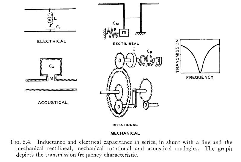 |
|
|
|
|
Jcman1ey
Registered User
Joined: 11 June 2025 Location: Bristol Status: Offline Points: 12 |
Post Options
Thanks(0)
Quote Reply
Posted: 02 October 2025 at 10:41am |
|
cheers
|
|
|
|
|
Post Reply
|
Page <12 |
| Tweet |
| Forum Jump | Forum Permissions You cannot post new topics in this forum You cannot reply to topics in this forum You cannot delete your posts in this forum You cannot edit your posts in this forum You cannot create polls in this forum You cannot vote in polls in this forum |


 Topic Options
 Here I’m posting a list of materials that are being used and recommended by some manufacturers, to hear your opinion on which would be the most suitable option: