
|
Turbosound Crossover Repair |
Post Reply 
|
| Author | |
Jake_Fielder 
Old Croc 
Joined: 08 October 2007 Status: Offline Points: 4236 |
 Post Options Post Options
") Thanks(0) Thanks(0)
 Quote Reply Quote Reply
 Topic: Turbosound Crossover Repair Topic: Turbosound Crossover RepairPosted: 24 September 2009 at 1:11am |
|
Just to help out others who get the HF failing on a Turbosound midtop. I think it was the 10" and 1" section of a TMS5, i assume this could be the same crossover as the TSE111 and other models with the same 10 + 1 horn module bit.
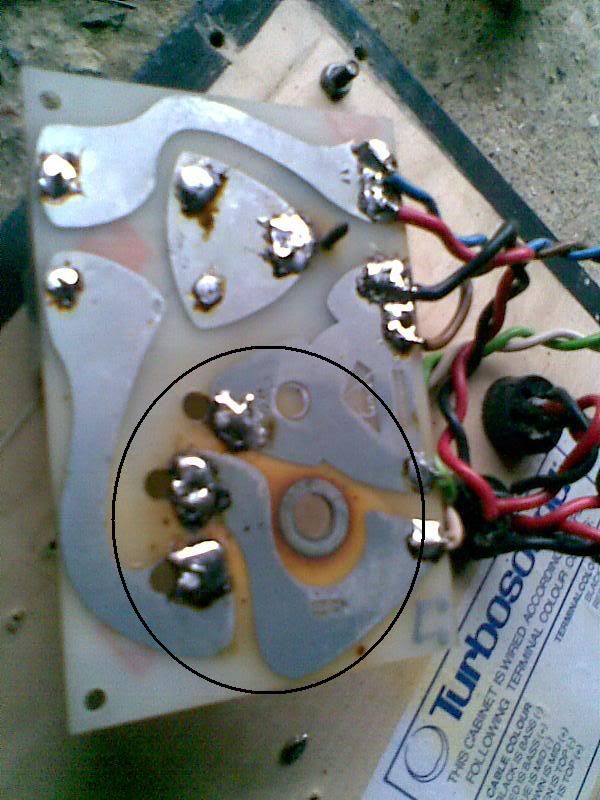
I repaired the HF Pot/Volume control/Attenuator, when i took it apart i could see the obvious burn marks, Where the attenuator was is circled black;
 Heres the inside of the attenuator, Circled blue is the burnt/blackened area, which was still ok, as it was a white insulating material that was the burnt colour, not the wire.
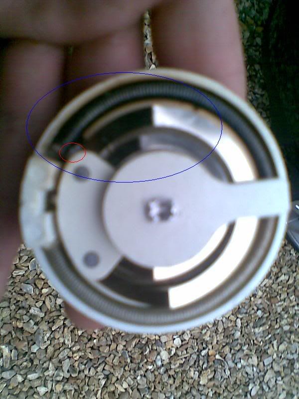 Circled in red is the problem area, all that had happened is the coil had gotten so hot that the solder had melted (must have been around 200 degrees), disconnecting the wire from the terminal, I simply soldered it back on... DONE
This is just for referance as hopefully searchers can find this and if they find similar symptoms* they can attempt this repair even with no electronic knowledge and only basic soldering skills. The Pot/ attenuator doesnt have to be reomoved from the circuit board.
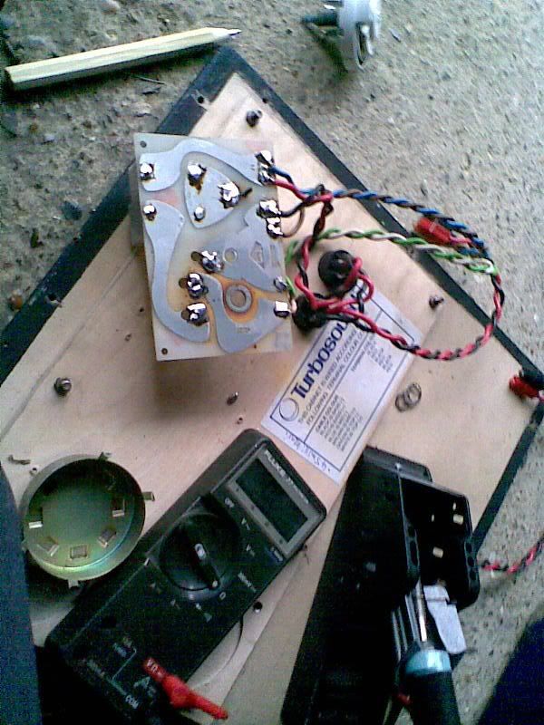
One more pic for good measure
 * symptoms as in, HF works on its own but not when used though the crossover, and burn marks around the volume control on the crossover circuit board.
Feel free to correct me on details like the model numbers as im a tad unsure
|
|
 |
|
|
Tedski
Registered User 
Joined: 15 December 2006 Location: Netherlands Status: Offline Points: 453 |
Post Options
Thanks(0)
Quote Reply
Posted: 24 September 2009 at 8:58am |
|
Very nice,
but in my experience, after a coil has gotten so hot, it no longer has the same properties as it did before, changing the x-over point. |
|
|
|
|
Jake_Fielder
Old Croc
Joined: 08 October 2007 Status: Offline Points: 4236 |
Post Options
Thanks(0)
Quote Reply
Posted: 24 September 2009 at 9:15am |
|
Realy? It would have to have a changed capacitance or inductance...? Why do you think this happens?
|
|
|
|
|
Tedski
Registered User
Joined: 15 December 2006 Location: Netherlands Status: Offline Points: 453 |
Post Options
Thanks(0)
Quote Reply
Posted: 24 September 2009 at 10:10am |
|
Not sure, but in the past I have had to replace passive x-overs after the 1" had blow.
All the energy that was meant to go to the 1", goes to the coil, heating it up. After replacing the 1", it sounded wrong, and had to replace all the coils on the passive x-overs to get it right again. They had visibly deformed and gone darker. |
|
|
|
|
hectorberman
Registered User

Joined: 25 May 2017 Status: Offline Points: 87 |
Post Options
Thanks(0)
Quote Reply
Posted: 04 May 2023 at 9:23pm |
|
Sorry to revive such an old thread, but can anyone tell me which of the wires out of green and white is positive and negative respectively?
|
|
|
|
|
Wikl109
Young Croc 
Joined: 29 April 2009 Location: Yorkshire Status: Offline Points: 982 |
Post Options
Thanks(0)
Quote Reply
Posted: 05 May 2023 at 8:25pm |
|
I've never used these particular cabs but looking at the bottom right corner of the first picture it seems to say:
CABLE COLOUR Black Is Bass (-) Red Is Bass (+) Blue Is Mid (-) Brown Is Mid (+) That means white and green are the only two left. Again looking at the picture it must be: Green Is Top (-) White Is Top (+) The only problem here is the soldering on the crossover looks like it may have been tampered with as it's not very neat. It may well be how they came from the factory though. I'm pretty certain that is what the plate says though so I'd go with that. |
|
|
Cheers, Chris.
|
|
|
|
|
hectorberman
Registered User
Joined: 25 May 2017 Status: Offline Points: 87 |
Post Options
Thanks(0)
Quote Reply
Posted: 11 May 2023 at 11:22am |
|
Here are the crossovers in question. I wanted to avoid creating a new thread so thought I'd ask this here too.
While the components differ slightly, as these are from two slightly different models of the same cabinet, one is completely missing a coil? Can anyone shed any light on what's going on here? Has someone removed it or was it never there?  |
|
|
|
|
RoadRunnersDust
Young Croc

Joined: 03 December 2013 Location: United Kingdom Status: Offline Points: 617 |
Post Options
Thanks(0)
Quote Reply
Posted: 21 May 2023 at 12:08pm |
|
If you google for Turbosound tms crossover you’ll find a scan of a hand drawn note by T.A. That will give you a schematic and values for what the TMS crossovers should be :)
|
|
|
|
|
Post Reply
|
|
| Tweet |
| Forum Jump | Forum Permissions You cannot post new topics in this forum You cannot reply to topics in this forum You cannot delete your posts in this forum You cannot edit your posts in this forum You cannot create polls in this forum You cannot vote in polls in this forum |


 Topic Options