|
tapped horn design |
Post Reply 
|
Page <1 789 |
| Author | |
philpope 
Registered User 
Joined: 21 January 2007 Location: United Kingdom Status: Offline Points: 42 |
 Post Options Post Options
") Thanks(0) Thanks(0)
 Quote Reply Quote Reply
 Posted: 05 March 2007 at 10:26am Posted: 05 March 2007 at 10:26am |
|
the way I have used hornresp is to model as an exponential horn. I use two sections - one which will be the section behind the driver tap and the second the rest of the horn in front of it. the first section should be approx 1/4 the total length but IMO there is a lot of leeway in this. I try to keep the flare contstant of the two sections roughly equal. I think when william said 2:1 compression ration he meant the ratio of Sd to the end of the horn NOT the cross section where the tap is. I assumed that the lowest bass response (which is what we are after with a tapped horn) would be obtained by tapping the driver into the horn where the cross section is the same as Sd so I make the throat of the second section in the model equal to Sd. If you want to use a much smaller horn then instead of increasing the compression ratio find a driver with a smaller Sd but same motor. Sd:mouth ratio should be about 1:3. I modelled in half space and aimed for 6dB-9dB of dip. start by deciding on a low cut off (which will roughly determine the total length) and a cabinet volume; choose an Sd and then play around with the mouth size (which is going to roughly determine the amount of gain and flare constant) and tap position and see if you can get it to work. then try and work out how to fold it! I actually started off by sketching different ways of folding them before I modelled anything. I think I have guessed the folding in three of the danley boxes and one by outline and have come up with a good one of my own. there are dozens of ways to do it but I think ones that have fewer bends near the mouth and avoid an access panel and let you see the cone excursion whilst in use are the most elegant. hope that all makes sense.
Phil |
|
 |
|
|
philpope
Registered User
Joined: 21 January 2007 Location: United Kingdom Status: Offline Points: 42 |
Post Options
Thanks(0)
Quote Reply
Posted: 05 March 2007 at 10:27am |
|
forgot to say - try doubling the Sd parameter in Hornresp and then overlay with the standard plot.
Phil |
|
|
|
|
philpope
Registered User
Joined: 21 January 2007 Location: United Kingdom Status: Offline Points: 42 |
Post Options
Thanks(0)
Quote Reply
Posted: 05 March 2007 at 10:31am |
|
just realised I didn't mention that I don't think using the combined response function in Hornresp is useful. the model is just going to tell you what the sensitivity will be, where the LF rolloff will begin, whether the dip is small enough that it might work, and whether the cabinet volume is manageable.
Phil |
|
|
|
|
Jeff Permanian
Registered User
Joined: 19 February 2007 Location: United States Status: Offline Points: 15 |
Post Options
Thanks(0)
Quote Reply
Posted: 27 March 2007 at 12:41pm |
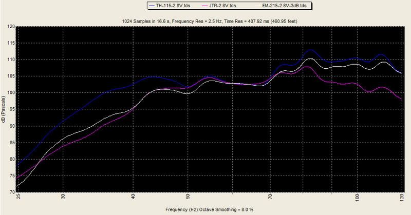
The growler isn't a tapped. Tom Danley sure can make speakers. Here's is a measurement from the prosound shootout with the TH-115, Growler and the EM-215. Keep in mind the Growler is half the size of the others!!!
 |
|
|
www.JTRSpeakers.com
847-714-6878 Jeff@jtrspeaker.com |
|
|
|
|
freddi
Registered User
Joined: 13 December 2006 Location: United Kingdom Status: Offline Points: 60 |
Post Options
Thanks(0)
Quote Reply
Posted: 27 March 2007 at 4:17pm |
|
hey Jeff - your hornsub looks real good for 42Hz - guess round thing in picture is access cover -? whats its input Z look like? Freddy
|
|
|
|
|
Jeff Permanian
Registered User
Joined: 19 February 2007 Location: United States Status: Offline Points: 15 |
Post Options
Thanks(0)
Quote Reply
Posted: 28 March 2007 at 11:56am |
|
|
|
www.JTRSpeakers.com
847-714-6878 Jeff@jtrspeaker.com |
|
|
|
|
philpope
Registered User
Joined: 21 January 2007 Location: United Kingdom Status: Offline Points: 42 |
Post Options
Thanks(0)
Quote Reply
Posted: 16 May 2007 at 10:36pm |
|
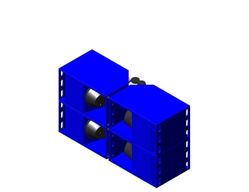
some pretty pictures from AutoCAD
 |
|
|
|
|
DJ Vencenzo
Registered User
Joined: 20 May 2007 Status: Offline Points: 18 |
Post Options
Thanks(0)
Quote Reply
Posted: 20 May 2007 at 11:14pm |
wow that almost looks like your spliting the first wave in half to make a total of 3 exiting the mouth.....maybe 1/16, 1/8, and 1/4....cool man!
|
|
|
|
|
DJ Vencenzo
Registered User
Joined: 20 May 2007 Status: Offline Points: 18 |
Post Options
Thanks(0)
Quote Reply
Posted: 06 June 2007 at 6:20pm |
|
bump
|
|
|
|
|
Post Reply
|
Page <1 789 |
| Tweet |
| Forum Jump | Forum Permissions You cannot post new topics in this forum You cannot reply to topics in this forum You cannot delete your posts in this forum You cannot edit your posts in this forum You cannot create polls in this forum You cannot vote in polls in this forum |


 Topic Options
 _djk_ wrote:
 What's with all the cookie securtiy issues?